
If you would like to build this but don't like the idea of starting completely from scratch, please check out Chris Davis' Altair-Duino kit which comes with all components, a PCB, a case and a pre-programmed Arduino Due!
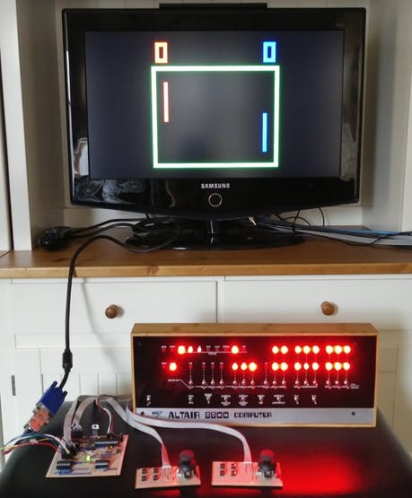
Here are some pictures from others who have built this project and made it their own:
If anybody else wants to share their creation let me know and I'll post it here. I'd love to see the variety of versions that people come up with!
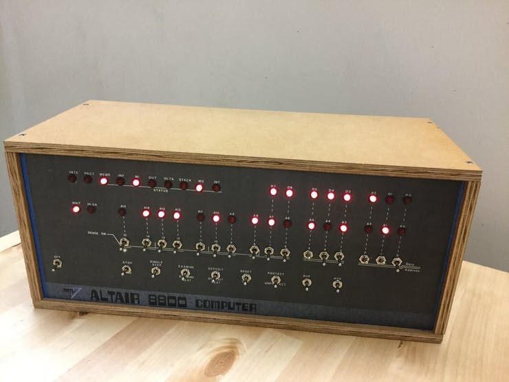
For a long time I have thought it would be cool to have an Altair 8800 computer to play around with. But working vintage Altairs are rare and therefore expensive, easily costing $1500-$2500 if available at all. There are some other options, such as altairclone.com but that still costs $600 which for me is too much to spend on a computer that - while very cool - will be of limited use. Thankfully Mike Douglas, the creator of the Altair Clone, has made available to the community all the old documents and software he hunted down and used when creating the clone. Thanks to Mike's work there is a wealth of information on the inner workings of the Altair and its most popular peripherals conveniently available.
Using the Arduino Mega to drive the simulator worked fine and was simple to set up but the emulation runs at only about 25% of the Altair's speed and it can only provide 6KB of emulated RAM (although back in the day that would have been a lot). Permanent storage capacity (for saving programs/data created in the simulator) is also limited since the Mega's EEPROM only holds 4KB.
The Arduino Due has plenty of memory to support a full 64KB of emulated RAM and runs much faster than the Mega. Additionally, the Due can save data to the flash memory at run time. That makes it possible to use any portion of the 512K flash not used by the simulator itself for permanent storage.
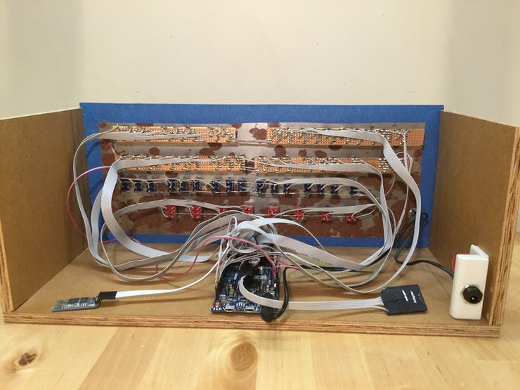
One goal was to use as little support circuitry as possible. Both the Arduino Mega and Due have enough I/O pins to directly wire up all the front panel elements. The only additional circuitry required are the transistors and resistors to drive the 36 LEDs (if the LEDs were connected directly to the Aruino's output pins and too many turned on at the same time the total current would exceed the Arduino's limits).
Creating full schematics for this project would be tedious, repetitive (36 identical LED driver circuits, wiring for 32 switches) and not very helpful. So the schematics document instead contains detailed tables about which elements get connected to which Arduino pins and the schematics for the individual sub-circuits (like LED drivers). I also added a Fritzing file to show the layout of the LED driver components on the stripboard.


