
This is the code for the Arduino based ESC. Downlaod the .zip file or copy+paste from below. Read all comments in the code in order to understand more. You have 2 files, the main .ino file and the EEPROMAnything file.
/* Title: ELECTRONOOBS open source electronic speed controller.
* Date: 02/04/2019
* Version: 3.3
* Author: http://electronoobs.com
* Tutorial link: https://www.electronoobs.com/eng_arduino_tut91.php
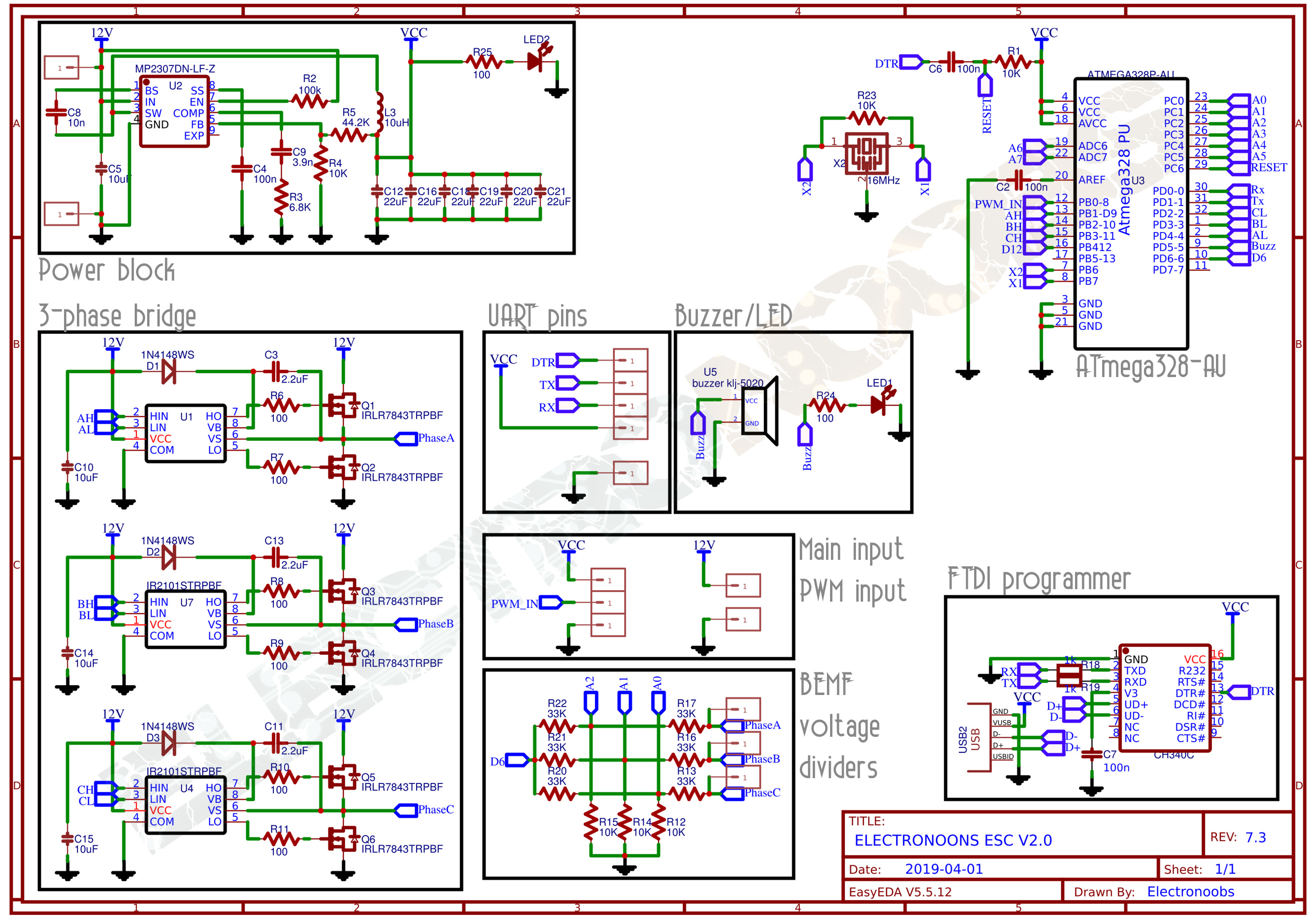
* Schematic link: https://www.electronoobs.com/eng_arduino_tut91_sch1.php
* PCB gerbers: https://www.electronoobs.com/eng_arduino_tut91_gerbers1.php
* This is a sensorless ESC based on Arduino with the ATmega328 chip. It uses
* BEMF with the internal comparator of the ATmega328 to detect the rotor position.
* The speed control is made by a PWM signal. Feel free to change it and improve
* it however you want
* Subscribe: http://youtube.com/c/ELECTRONOOBS */
#include "EEPROMAnything.h" //This is used to store more than just one byte to the EEPROM
//Inputs/Outputs
int buzzer = 5;
/* PWM in pin - D8
* High A - D9
* LOW A - D4
* HIGH B - D10
* LOW B - D3
* HIGH C - D11
* LOW C - D2
* Comparator - D6
*/
#define PWM_max_value 255
#define PWM_min_value 30
#define PWM_value 50
int PWM_IN_MAX = 2000;
int PWM_IN_MIN = 1000;
int PWM_IN_MIN_ADRESS = 2;
int PWM_IN_MAX_ADRESS = 7;
int MIN_PWM_TO_STORE = 0;
int MAX_PWM_TO_STORE = 0;
int pwm_set_counter = 0;
int beeping_PWM_VALUE = 100;
byte sequence_step = 0, motor_speed;
unsigned int i;
//We create variables for the time width value of the PWM input signal
unsigned long counter_1, current_count;
byte last_PWM_state;
//To store the 1000us to 2000us value we create variables
int PWM_INPUT; //In my case PWM_IN pin is D8 of the Arduino
bool MOTOR_SPINNING = false;
bool ESC_MODE_ON = false;
int motor_off_counter = 0;
bool PWM_RANGE_SET = false;
unsigned long previousMillis = 0;
unsigned long currentMillis = 0;
void setup() {
pinMode(buzzer,OUTPUT);
//This will only run once after you uplaod the code
if( EEPROM.read(1) != 1)
{
EEPROM_writeAnything(PWM_IN_MIN_ADRESS, PWM_IN_MIN);
EEPROM_writeAnything(PWM_IN_MAX_ADRESS, PWM_IN_MAX);
EEPROM.write(1, 1);
}
Serial.begin(9600);
//#error first time you uplaod the code make sure the enxt lien is uncommented. Then, comment back the line and uplaod the code again and delete this entire error line
//EEPROM.write(1, 0);
//Our pins for the MNSFET drivers are 2,3,4 and 9,10,11
DDRD |= B00011100; //Configure pins 2, 3 and 4 as outputs CL, BL and AL
PORTD = B00000000; //Pins 0 to 7 set to LOW
DDRB |= B00001110; //Configure pins 9, 10 and 11 as outputs
PORTB &= B00110001; //D9, D10 and D11 to LOW
// Timer1
TCCR1A = 0;
TCCR1B = 0x01;
// Timer2
TCCR2A = 0;
TCCR2B = 0x01;
// Comparator on pin D6
ACSR = 0x10; // Clear flag comparator interrupt
//Set D8 (PWM in) to trigger interrupt (we use this to read PWM input)
PCICR |= (1 << PCIE0); //enable PCMSK0 scan
PCMSK0 |= (1 << PCINT0); //Set pin D8 trigger an interrupt on state change.
/*Now we detect the PWM input and if is higher than we enter
configuration mode and if not, we jump to the void loop*/
delay(200);
//Power on mode select
if(PWM_INPUT > PWM_IN_MIN + 115)
{
ESC_MODE_ON = false; //Motor rotation is OFF till the config mode is done
while(!PWM_RANGE_SET)
{
currentMillis = millis();
if(currentMillis - previousMillis >= 500)
{
OCR1A = beeping_PWM_VALUE;
previousMillis += 500;
digitalWrite(buzzer,HIGH);
PORTD = B00010000; //Set D4 to HIGH and the rest to LOW
TCCR1A = 0x81; //OC1A - D9 compare match noninverting mode, downcounting ,PWM 8-bit
delay(100);
digitalWrite(buzzer,LOW);
PORTD = B00000000; //Set D4 to HIGH and the rest to LOW
TCCR1A = 0; // OC1A and OC1B normal port
}
if(PWM_INPUT > MAX_PWM_TO_STORE)
{
MAX_PWM_TO_STORE = PWM_INPUT;
}
if(PWM_INPUT < 1200)
{
if(pwm_set_counter > 1000)
{
MIN_PWM_TO_STORE = PWM_INPUT;
EEPROM_writeAnything(PWM_IN_MIN_ADRESS, MIN_PWM_TO_STORE);
EEPROM_writeAnything(PWM_IN_MAX_ADRESS, MAX_PWM_TO_STORE);
ESC_MODE_ON = true;
PWM_RANGE_SET = true;
int y = 0;
digitalWrite(buzzer,HIGH);
PORTD = B00010000; //Set D4 to HIGH and the rest to LOW
TCCR1A = 0x81; //OC1A - D9 compare match noninverting mode, downcounting ,PWM 8-bit
delay(500);
digitalWrite(buzzer,LOW);
PORTD = B00000000; //Set D4 to HIGH and the rest to LOW
TCCR1A = 0; //OC1A - D9 compare match noninverting mode, downcounting ,PWM 8-bit
delay(200);
while(y < 3)
{
digitalWrite(buzzer,HIGH);
PORTD = B00010000; //Set D4 to HIGH and the rest to LOW
TCCR1A = 0x81; //OC1A - D9 compare match noninverting mode, downcounting ,PWM 8-bit
delay(100);
digitalWrite(buzzer,LOW);
PORTD = B00000000; //Set D4 to HIGH and the rest to LOW
TCCR1A = 0; //OC1A - D9 compare match noninverting mode, downcounting ,PWM 8-bit
delay(100);
y = y + 1;
}
}
pwm_set_counter = pwm_set_counter + 1;
delay(1);
}
else
{
pwm_set_counter = 0;
}
}//end of !PWM_RANGE_SET
}
/*If the range is below PWM_IN_MIN+115us then we start the code*/
else
{
OCR1A = beeping_PWM_VALUE;
ESC_MODE_ON = true;
int x = 0;
digitalWrite(buzzer,HIGH);
PORTD = B00010000; //Set D4 to HIGH and the rest to LOW
TCCR1A = 0x81; //OC1A - D9 compare match noninverting mode, downcounting ,PWM 8-bit
delay(500);
digitalWrite(buzzer,LOW);
PORTD = B00000000; //Set D4 to HIGH and the rest to LOW
TCCR1A = 0; //OC1A - D9 compare match noninverting mode, downcounting ,PWM 8-bit
delay(200);
while(x < 3)
{
digitalWrite(buzzer,HIGH);
PORTD = B00010000; //Set D4 to HIGH and the rest to LOW
TCCR1A = 0x81; //OC1A - D9 compare match noninverting mode, downcounting ,PWM 8-bit
delay(100);
digitalWrite(buzzer,LOW);
PORTD = B00000000; //Set D4 to HIGH and the rest to LOW
TCCR1A = 0; //OC1A - D9 compare match noninverting mode, downcounting ,PWM 8-bit
delay(100);
x = x + 1;
}
}
//Save new range to the EEPROM
EEPROM_readAnything(PWM_IN_MIN_ADRESS, PWM_IN_MIN);
EEPROM_readAnything(PWM_IN_MAX_ADRESS, PWM_IN_MAX);
}//End of setup loop
// Interrumption vector for the Analog comparator
ISR (ANALOG_COMP_vect) {
for(i = 0; i < 10; i++) { //We check the comparator 10 times just to be sure
if(sequence_step & 1) //If step = odd (0001, 0011, 0101) 1, 3 or 5
{
if(!(ACSR & B00100000)) i -= 1; //!B00100000 -> B11011111 ACO = 0 (Analog Comparator Output = 0)
}
else //else if step is 0, 2 or 4
{
if((ACSR & B00100000)) i -= 1; //else if B00100000 -> B11011111 ACO = 1 (Analog Comparator Output = 1)
}
}
set_next_step(); //set the next step of the sequence
sequence_step++; //increment step by 1, next part of the sequence of 6
sequence_step %= 6; //If step > 5 (equal to 6) then step = 0 and start over
}
//Switch to next step functions
void set_next_step(){
switch(sequence_step){
case 0:
AH_BL();
BEMF_C_RISING();
break;
case 1:
AH_CL();
BEMF_B_FALLING();
break;
case 2:
BH_CL();
BEMF_A_RISING();
break;
case 3:
BH_AL();
BEMF_C_FALLING();
break;
case 4:
CH_AL();
BEMF_B_RISING();
break;
case 5:
CH_BL();
BEMF_A_FALLING();
break;
}
}//end of set_next_step
//main loop
void loop() {
/*if PWM input is higher than PWM_IN_MIN + 115 we start the motor*/
if(PWM_INPUT > (PWM_IN_MIN + 115) && ESC_MODE_ON)
{
MOTOR_SPINNING = true;
motor_off_counter = 0;
digitalWrite(buzzer,LOW);
}
//////////////////////////Motor is rotating////////////////////////
if(MOTOR_SPINNING)
{
SET_PWM(PWM_value); // Setup starting PWM with duty cycle = PWM_START_DUTY
i = 2200;
// Motor start
while(i > 100) {
delayMicroseconds(i);
set_next_step();
sequence_step++;
sequence_step %= 6;
i = i - 20;
}
motor_speed = PWM_value;
ACSR |= 0x08; // Enable analog comparator interrupt
while(MOTOR_SPINNING)
{
PWM_INPUT = constrain(PWM_INPUT,PWM_IN_MIN,PWM_IN_MAX);
motor_speed = map(PWM_INPUT,PWM_IN_MIN,PWM_IN_MAX,PWM_min_value,PWM_max_value);
SET_PWM(motor_speed);
if(PWM_INPUT < (PWM_IN_MIN + 30))
{
if(motor_off_counter > 1000)
{
MOTOR_SPINNING = false;
motor_off_counter = 0;
PORTD = B00000000; //Set D4 to HIGH and the rest to LOW
TCCR1A = 0; //OC1A - D9 compare match noninverting mode, downcounting ,PWM 8-bit
}
motor_off_counter = motor_off_counter + 1;
}
//Serial.print(PWM_IN_MIN);Serial.print(" ");Serial.println(PWM_IN_MAX);
//Serial.println(motor_speed);
}
}//end of if MOTOR_SPINNING
//////////////////////////Motor STOP////////////////////////
if(!MOTOR_SPINNING)
{
unsigned long currentMillis = millis();
if(currentMillis - previousMillis >= 2000){
//previousMillis += 2000;
digitalWrite(buzzer,HIGH);
ACSR = 0x10; // Disable and clear (flag bit) analog comparator interrupt
TCCR2A = 0;
TCCR1A = 0;
PORTD = 0x00; //pins 0 to 7 set to LOW //stop everything
PORTB &= 0x31; //B00110001 D9, D10 and D11 to LOW
OCR1A = beeping_PWM_VALUE;
PORTD = B00010000; //Set D4 to HIGH and the rest to LOW
TCCR1A = 0x81; //OC1A - D9 compare match noninverting mode, downcounting ,PWM 8-bit
}
if(currentMillis - previousMillis >= 2100){
previousMillis += 2000;
digitalWrite(buzzer,LOW);
PORTD = B00000000; //All to LOW
TCCR1A = 0; //PWM disabled
}
}//end of if !MOTOR_SPINNING
}//end of void loop
/*On each step we know that the next 0 cross will be rising or falling and if it will be
on coil A, B or C. With these funcstions we select that according to the step of the sequence*/
void BEMF_A_RISING(){
ADCSRA = (0 << ADEN); // Disable the ADC module
ADCSRB = (1 << ACME); // MUX select for negative input of comparator
ADMUX = 2; // Select A2 as comparator negative input
ACSR |= 0x03; // Set interrupt on rising edge*/
}
void BEMF_A_FALLING(){
ADCSRA = (0 << ADEN); // Disable the ADC module
ADCSRB = (1 << ACME); // MUX select for negative input of comparator
ADMUX = 2; // Select A2 as comparator negative input
ACSR &= ~0x01; // Set interrupt on falling edge*/
}
void BEMF_B_RISING(){
ADCSRA = (0 << ADEN); // Disable the ADC module
ADCSRB = (1 << ACME); // MUX select for negative input of comparator
ADMUX = 1; // Select A1 as comparator negative input
ACSR |= 0x03; // Set interrupt on rising edge
}
void BEMF_B_FALLING(){
ADCSRA = (0 << ADEN); // Disable the ADC module
ADCSRB = (1 << ACME); // MUX select for negative input of comparator
ADMUX = 1; // Select A1 as comparator negative input
ACSR &= ~0x01; // Set interrupt on falling edge*/
}
void BEMF_C_RISING(){
ADCSRA = (0 << ADEN); // Disable the ADC module
ADCSRB = (1 << ACME); // MUX select for negative input of comparator
ADMUX = 0; // Select A0 as comparator negative input
ACSR |= 0x03; // Set interrupt on rising edge
}
void BEMF_C_FALLING(){
ADCSRA = (0 << ADEN); // Disable the ADC module
ADCSRB = (1 << ACME); // MUX select for negative input of comparator
ADMUX = 0; // Select A0 as comparator negative input
ACSR &= ~0x01; // Set interrupt on falling edge*/
}
/*On each step we change the digital pins to be HIGH or LOW or to be PWM or no-PWM
depending on which step of the sequence we are*/
//D9 PWM and D3 HIGH.
void AH_BL(){
PORTD = B00001000; //Set D3 (BL) to HIGH and the rest to LOW
TCCR2A = 0; //OC2A - D11 normal port.
TCCR1A = 0x81; //OC1A - D9 (AH) compare match noninverting mode, downcounting ,PWM 8-bit
}
//D9 PWM and D2 HIGH
void AH_CL(){
PORTD = B00000100; //Set D2 (CL) to HIGH and the rest to LOW
TCCR2A = 0; //OC2A - D11 normal port.
TCCR1A = 0x81; //OC1A - D9 (AH) compare match noninverting mode, downcounting ,PWM 8-bit
}
//D10 PWM and D2 HIGH
void BH_CL(){
PORTD = B00000100; //Set D2 (CL) to HIGH and the rest to LOW
TCCR2A = 0; //OC2A - D11 normal port.
TCCR1A = 0x21; //OC1B - D10 (BH) compare match noninverting mode, downcounting ,PWM 8-bit
}
//D10 PWM and D4 HIGH
void BH_AL(){
PORTD = B00010000; //Set D4 (AL) to HIGH and the rest to LOW
TCCR2A = 0; //OC2A - D11 normal port.
TCCR1A = 0x21; //OC1B - D10 (BH) compare match noninverting mode, downcounting ,PWM 8-bit
}
//D11 PWM and D4 HIGH
void CH_AL(){
PORTD = B00010000; //Set D4 (AL) to HIGH and the rest to LOW
TCCR1A = 0; // OC1A and OC1B normal port
TCCR2A = 0x81; // OC2A - D11 (CH) compare match noninverting mode, downcounting ,PWM 8-bit
}
//D11 PWM and D3 HIGH
void CH_BL(){
PORTD = B00001000; //Set D3 (BL) to HIGH and the rest to LOW
TCCR1A = 0; // OC1A and OC1B normal port
TCCR2A = 0x81; // OC2A - D11 (CH) compare match noninverting mode, downcounting ,PWM 8-bit
}
/*This function will only change the PWM values according to the received width_value
that is given by the PWM read on pin D8*/
void SET_PWM(byte width_value){
//We keep the range of PWM between min and max (8 bit value)
if(width_value < PWM_min_value) width_value = PWM_min_value;
if(width_value > PWM_max_value) width_value = PWM_max_value;
OCR1A = width_value; // Set pin 9 PWM duty cycle
OCR1B = width_value; // Set pin 10 PWM duty cycle
OCR2A = width_value; // Set pin 11 PWM duty cycle
}
/*This is the interruption routine on pin change
in this case for digital pin D8 which is the PWM input*/
ISR(PCINT0_vect){
//First we take the current count value in micro seconds using the micros() function
current_count = micros();
///////////////////////////////////////Channel 1
if(PINB & B00000001){ //We make an AND with the pin state register, We verify if pin 8 is HIGH???
if(last_PWM_state == 0){ //If the last state was 0, then we have a state change...
last_PWM_state = 1; //Store the current state into the last state for the next loop
counter_1 = current_count; //Set counter_1 to current value.
}
}
else if(last_PWM_state == 1){ //If pin 8 is LOW and the last state was HIGH then we have a state change
last_PWM_state = 0; //Store the current state into the last state for the next loop
PWM_INPUT = current_count - counter_1; //We make the time difference. PWM_INPUT is current_time - counter_1 in micro-seconds.
}
}
#include <EEPROM.h>
#include <Arduino.h>  // for type definitions

template <class T> int EEPROM_writeAnything(int ee, const T& value)
{
    const byte* p = (const byte*)(const void*)&value;
    unsigned int i;
    for (i = 0; i < sizeof(value); i++)
          EEPROM.write(ee++, *p++);
    return i;
}

template <class T> int EEPROM_readAnything(int ee, T& value)
{
    byte* p = (byte*)(void*)&value;
    unsigned int i;
    for (i = 0; i < sizeof(value); i++)
          *p++ = EEPROM.read(ee++);
    return i;
}
void beep_1KHZ (int milliseconds)
{
  int x = 0;
  PORTD = B00001000;      //Set D2 (CL) to HIGH and the rest to LOW
  while (x < milliseconds)
  {
    PORTB = B00000010;      //Set D90 (AH) to HIGH (BH) to LOW
    delayMicroseconds(50);
    PORTB = B00000000;      //Set D90 (AH) to HIGH (BH) to LOW
    delayMicroseconds(450);

    PORTB = B00000100;      //Set D10 (BH) to HIGH (AH) to LOW
    delayMicroseconds(50);
    PORTB = B00000000;      //Set D10 (BH) to HIGH (AH) to LOW
    delayMicroseconds(450);
    x = x + 1;
  }
   PORTD = B00000000;      //Set D2 (CL) to HIGH and the rest to LOW
   PORTB = B00000000;      //Set D10 (BH) to HIGH (AH) to LOW
}


void beep_2KHZ (int milliseconds)
{
  int x = 0;
  PORTD = B00001000;      //Set D2 (CL) to HIGH and the rest to LOW
  while (x < milliseconds)
  {
    PORTB = B00000010;      //Set D90 (AH) to HIGH (BH) to LOW
    delayMicroseconds(50);
    PORTB = B00000000;      //Set D90 (AH) to HIGH (BH) to LOW
    delayMicroseconds(200);

    PORTB = B00000100;      //Set D10 (BH) to HIGH (AH) to LOW
    delayMicroseconds(50);
    PORTB = B00000000;      //Set D10 (BH) to HIGH (AH) to LOW
    delayMicroseconds(200);
    x = x + 1;
  }
   PORTD = B00000000;      //Set D2 (CL) to HIGH and the rest to LOW
   PORTB = B00000000;      //Set D10 (BH) to HIGH (AH) to LOW
}


void beep_3KHZ (int milliseconds)
{
  int x = 0;
  PORTD = B00001000;      //Set D2 (CL) to HIGH and the rest to LOW
  while (x < milliseconds)
  {
    PORTB = B00000010;      //Set D90 (AH) to HIGH (BH) to LOW
    delayMicroseconds(50);
    PORTB = B00000000;      //Set D90 (AH) to HIGH (BH) to LOW
    delayMicroseconds(150);

    PORTB = B00000010;      //Set D90 (AH) to HIGH (BH) to LOW
    delayMicroseconds(50);
    PORTB = B00000000;      //Set D90 (AH) to HIGH (BH) to LOW
    delayMicroseconds(150);

    PORTB = B00000010;      //Set D90 (AH) to HIGH (BH) to LOW
    delayMicroseconds(50);
    PORTB = B00000000;      //Set D90 (AH) to HIGH (BH) to LOW
    delayMicroseconds(150);

    PORTB = B00000010;      //Set D90 (AH) to HIGH (BH) to LOW
    delayMicroseconds(50);
    PORTB = B00000000;      //Set D90 (AH) to HIGH (BH) to LOW
    delayMicroseconds(150);

    PORTB = B00000010;      //Set D90 (AH) to HIGH (BH) to LOW
    delayMicroseconds(50);
    PORTB = B00000000;      //Set D90 (AH) to HIGH (BH) to LOW
    delayMicroseconds(150);
    x = x + 1;
  }
   PORTD = B00000000;      //Set D2 (CL) to HIGH and the rest to LOW
   PORTB = B00000000;      //Set D10 (BH) to HIGH (AH) to LOW
}
//Inputs/Outputs
int buzzer = 5;
/* PWM in pin - D8
 * High A - D9
 * LOW A - D4
 * HIGH B - D10
 * LOW B - D3
 * HIGH C - D11
 * LOW C - D2
 * Comparator - D6
*/
#define PWM_max_value      255
#define PWM_min_value      35
#define PWM_value    35


int PWM_IN_MAX = 2000;
int PWM_IN_MIN = 1000;
int PWM_IN_MIN_ADRESS = 2;
int PWM_IN_MAX_ADRESS = 7;
int MIN_PWM_TO_STORE = 0;
int MAX_PWM_TO_STORE = 0;
int pwm_set_counter = 0;
int beeping_PWM_VALUE = 100;

byte sequence_step = 0, motor_speed;
unsigned int i;
//We create variables for the time width value of the PWM input signal
unsigned long counter_1, current_count;
byte last_PWM_state;
//To store the 1000us to 2000us value we create variables
int PWM_INPUT;      //In my case PWM_IN pin is D8 of the Arduino
bool MOTOR_SPINNING = false;
bool ESC_MODE_ON = false;
int motor_off_counter = 0;
bool PWM_RANGE_SET = false;
unsigned long previousMillis = 0;
unsigned long currentMillis = 0;
bool full_stop = false;


