A Hall sensor is a device that allows us to perform magnetic field measurements.
Hall sensors are widely used. For example, in the automotive industry, they are used for the functions of the safety vehicle, or the measurement of the position of the camshaft. They are also used to measure fluid velocities, metal detection, induction factors, among many other applications.
An important advantage of Hall sensors is that they perform the measurement remotely, without the need for physical contact. Although its scope is limited. They are also immune to noise and dust. This translates into reliable and durable sensors.
Its operating principle is the Hall effect, named after its discoverer Edwin Herbery Hall, in 1849. By circulating an electric current along a semiconductor in the presence of a magnetic field, the electrons are deflected by the effect of the magnetic field, giving rise to a voltage perpendicular to the current and the magnetic field.
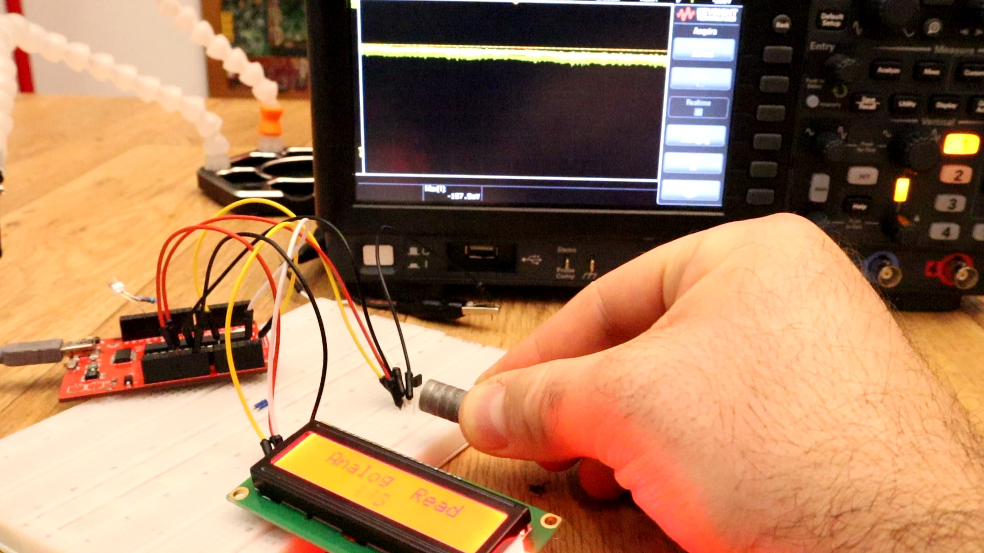
In order to calculate the magnetic field from the measurement, we first measure the voltage using an analogue Arduino input. Next we convert the voltage into magnetic flux density using the formula we have previously interpolated. We print the values on the serial monitor or LCD. See codes below.
const int pinHall = A0;
void setup() {
  pinMode(pinHall, INPUT);
  Serial.begin(9600);
}
void loop() {

  //we measure 10 times adn make the mean
  long measure = 0;
  for(int i = 0; i < 10; i++){
      int value =
      measure += analogRead(pinHall);
  }
  measure /= 10;
  //voltage in mV
  float outputV = measure * 5000.0 / 1023;
  Serial.print("Output Voltaje = ");
  Serial.print(outputV);
  Serial.print(" mV   ");

  //flux density
  float magneticFlux =  outputV * 53.33 - 133.3;
  Serial.print("Magnetic Flux Density = ");
  Serial.print(magneticFlux);
  Serial.print(" mT");
  delay(2000);
}
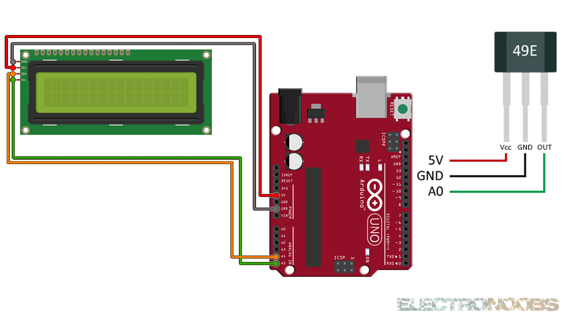
Upload the code and make the connections. Then open the serial monitor at 9600 bauds and you will have the results printed to the serial monitor. Or go below and download the code with the i2c LCD.
#include <Wire.h>
#include <LiquidCrystal_I2C.h>
// Set the LCD address to 0x27 or 0x3f for a 16 chars and 2 line display
LiquidCrystal_I2C lcd(0x27, 20, 4);

const int pinHall = A0;
void setup() {
  lcd.init();
  lcd.backlight();
  pinMode(pinHall, INPUT);
  Serial.begin(9600);
}

void loop() {

  //we measure 10 times adn make the mean
  long measure = 0;
  for(int i = 0; i < 10; i++){
      int value =
      measure += analogRead(pinHall);
  }
  measure /= 10;
  //voltage in mV
  float outputV = measure * 5000.0 / 1023;
  Serial.print("Output Voltaje = ");
  Serial.print(outputV);
  Serial.print(" mV   ");
  lcd.clear();
  lcd.setCursor(0,0);
  lcd.print("Vots: ");
  lcd.setCursor(6,0);
  lcd.print(outputV);


  //flux density
  float magneticFlux =  outputV * 53.33 - 133.3;
  Serial.print("Magnetic Flux Density = ");
  Serial.print(magneticFlux);
  Serial.print(" mT");
  lcd.setCursor(0,1);
  lcd.print("Flux: ");
  lcd.setCursor(6,1);
  lcd.print(magneticFlux);
  delay(2000);
}
Upload the code and make the connections. Then open the serial monitor at 9600 bauds or just see the results on the LCD screen.