I've been working on an Arduino based smartwatch that could show time, date, alarm, temperature, connect to a smartphone via Bluetooth and show notifications. I had some errors on this baord, but in this tutorial, I'm sharing the good board that I've already fixed. See below all the files, the GERBERS, the code and a step by tep tutorial. Lets start!
Here you haev the board used in this project. You could see the EasyEDA project link below or downlaod the GERBER file as well. Just downlaod the .zip file and send it to a PCB manufacturer. Once you receive the PCB check if for shorts, good tracks and connections. The board is double layer and it has a lot of small SMD components. Go below in this tutorial to see the full part list for all the components and also check the schematic below for all the values.
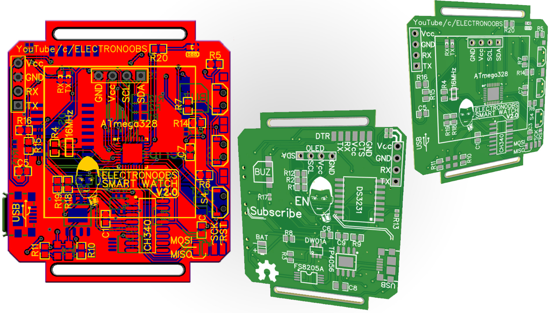
Below you have the schematic of this project. Have it in front of you while soldering the components so you know the value of each resistor/capacitor. The resistors that are of value "0" are just a solder connection. The circuit includes the charging part, FTDI programmer for the chip and buttons, buzzer, LEDs. It uses the ATmega328 chip that
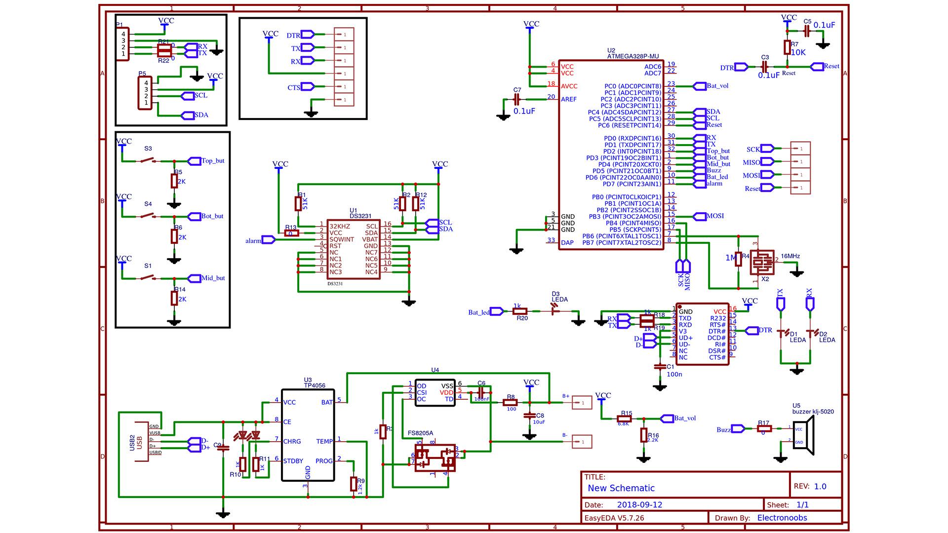
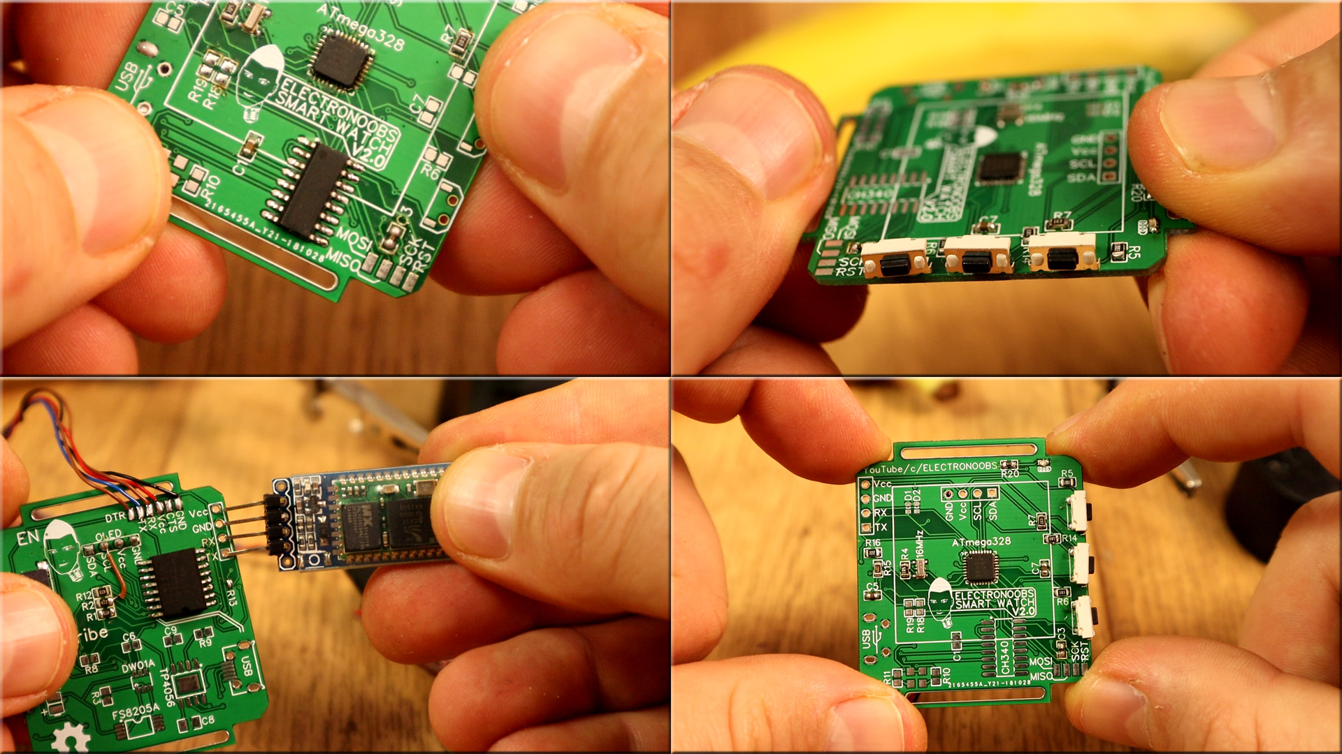
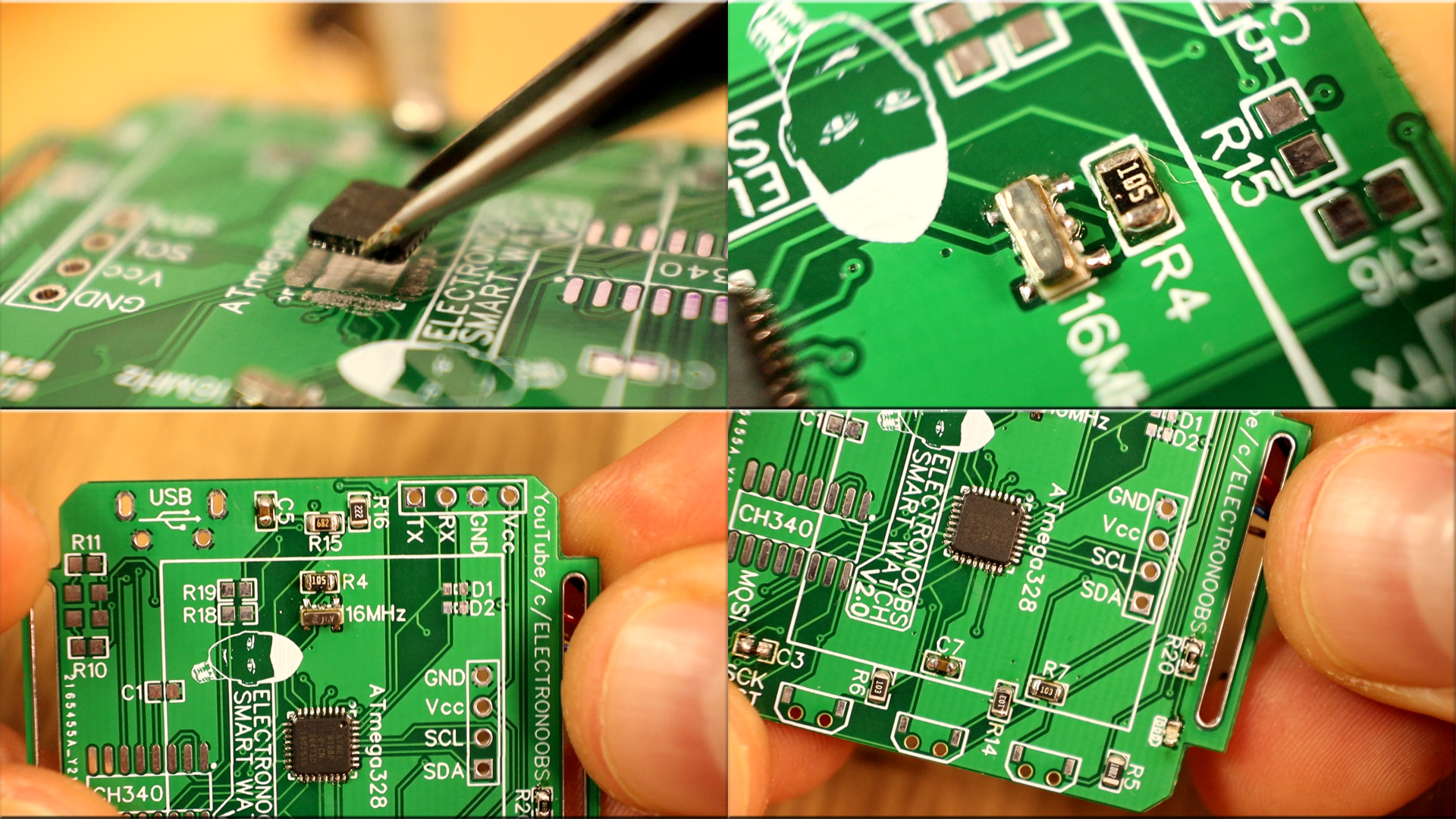
As always, when using the ATmega microcontroller, we have to make sure it works since it is the most important thing. The basic configuration of this chip is made by the R7 pullup resistor of 10K, the C3 DTR capacitor of 100nF, the R4 resistor for the crystal of 1M ohms and the 16Mhz crystal. With these components, we could test the chip so first thing firt solder the chip and these components to the PCB. Be careful soldering the small QFN chip and after you solder everything check for shorts between pins with a multimeter.
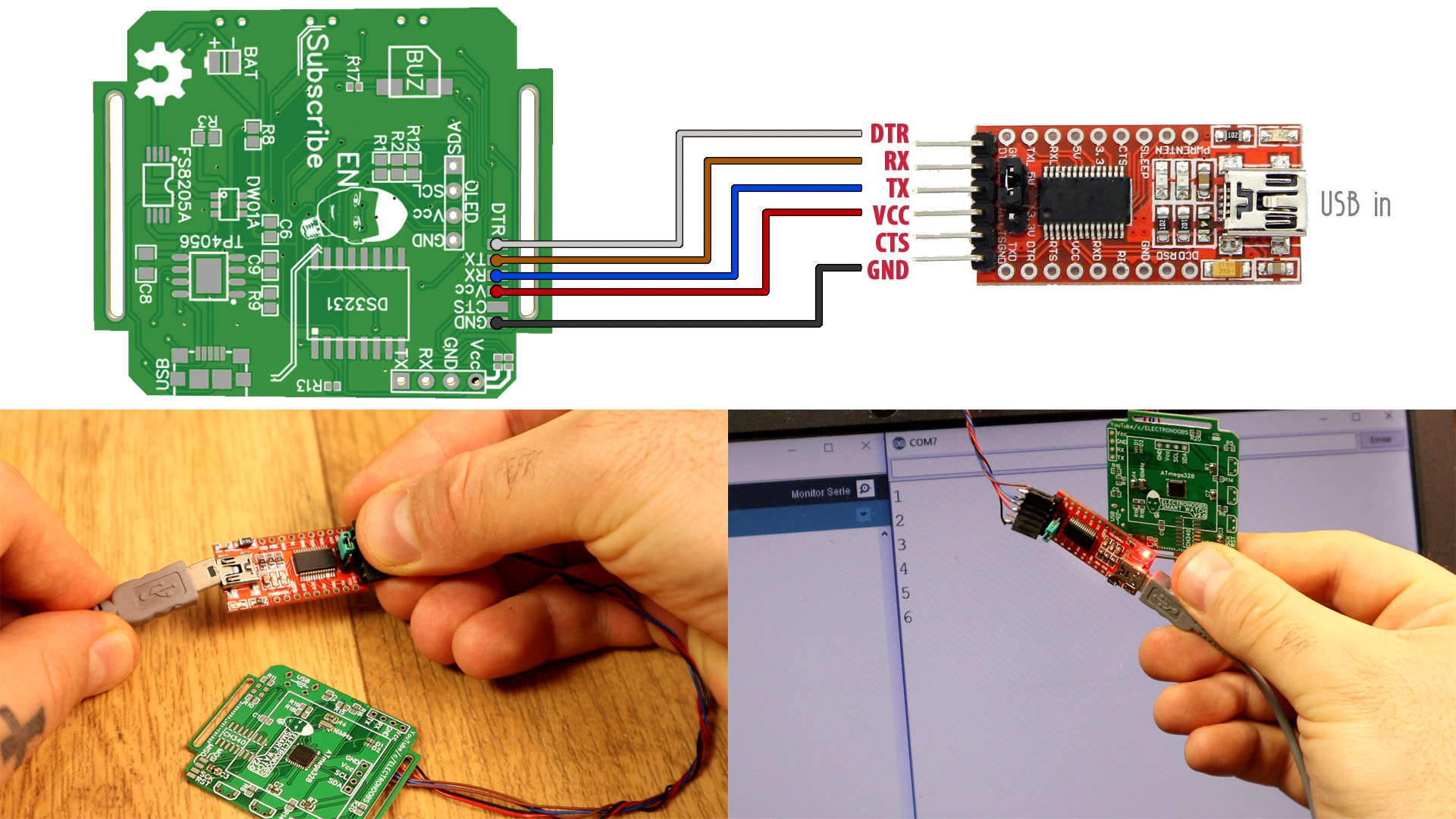
Now we have the basic configuration soldered. Connect an FTDI module like this one to the UART pins on the back layer of the PCB as you can see below. Then, open Arduino IDE and copy the code below that will just write something to the serial monitor. Select the COM of the programmer, select Arduino NANO board and after you uplaod the code, open serial monitor. You should receive the countup from 0, 1, 2...
int x  = 0;
void setup() {
  Serial.begin(9600);
}

void loop() {
  Serial.println(x);
  x = x + 1;
  delay(1000);
}
Ok, if you receive data, then the ATmega328 chip works. We can now solder the rest of the components.
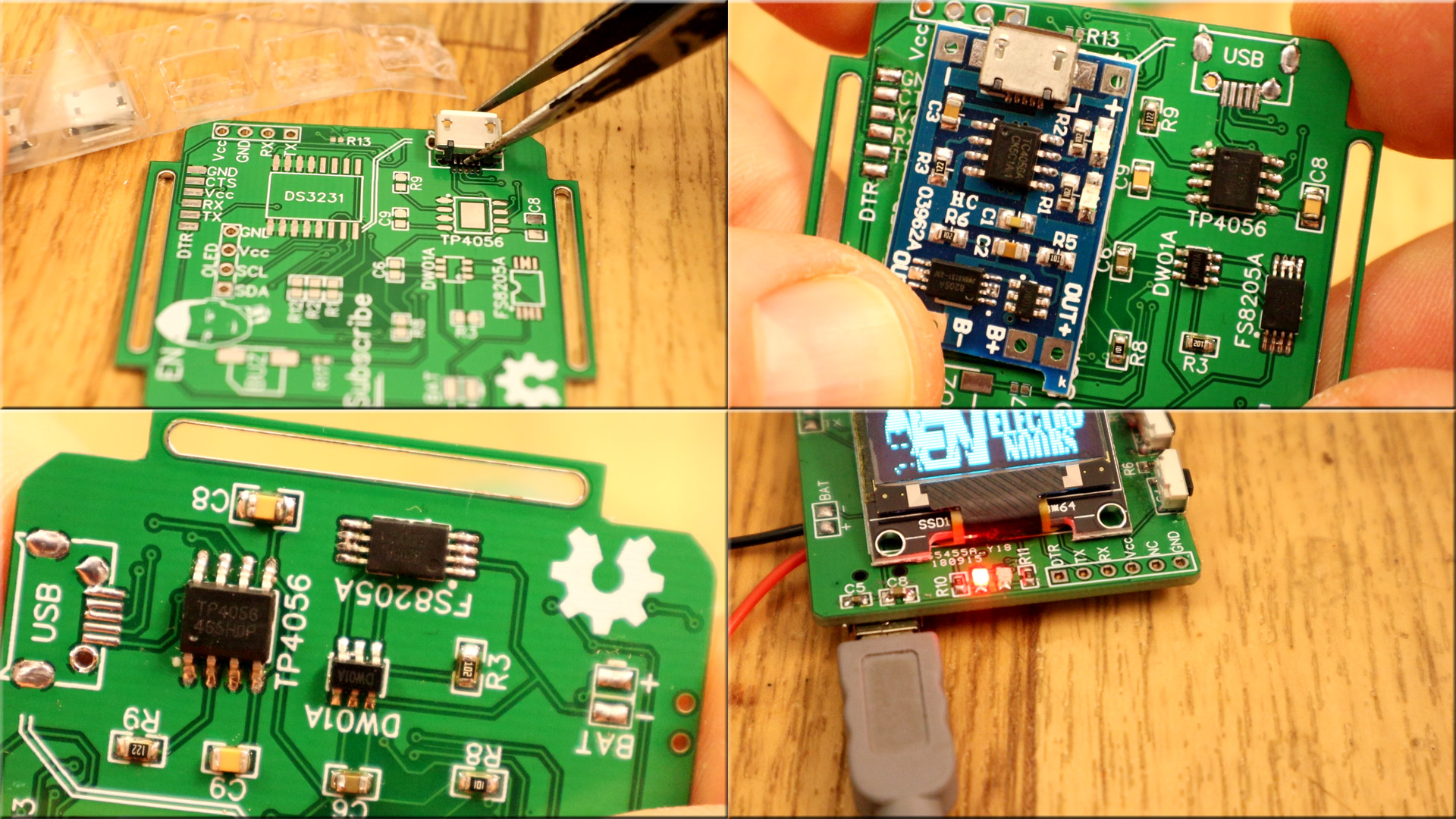
Once you have the circuit soldered, connect the LIPO battery of 3.7V to the BAT+ and BAT- pads. Then connect the USB connector and see if the LEDs of charging will turn on. In my case, I have a red LED for charging and a blue one for battery full. Now we can solder the rest of the components. Don't solder the Bluetooth adn OLED dispaly yet. Solder the FTDI mdoule, THE RTL (real time clock) chip, the buzzer, the push buttons and all the capacitors and resistors.