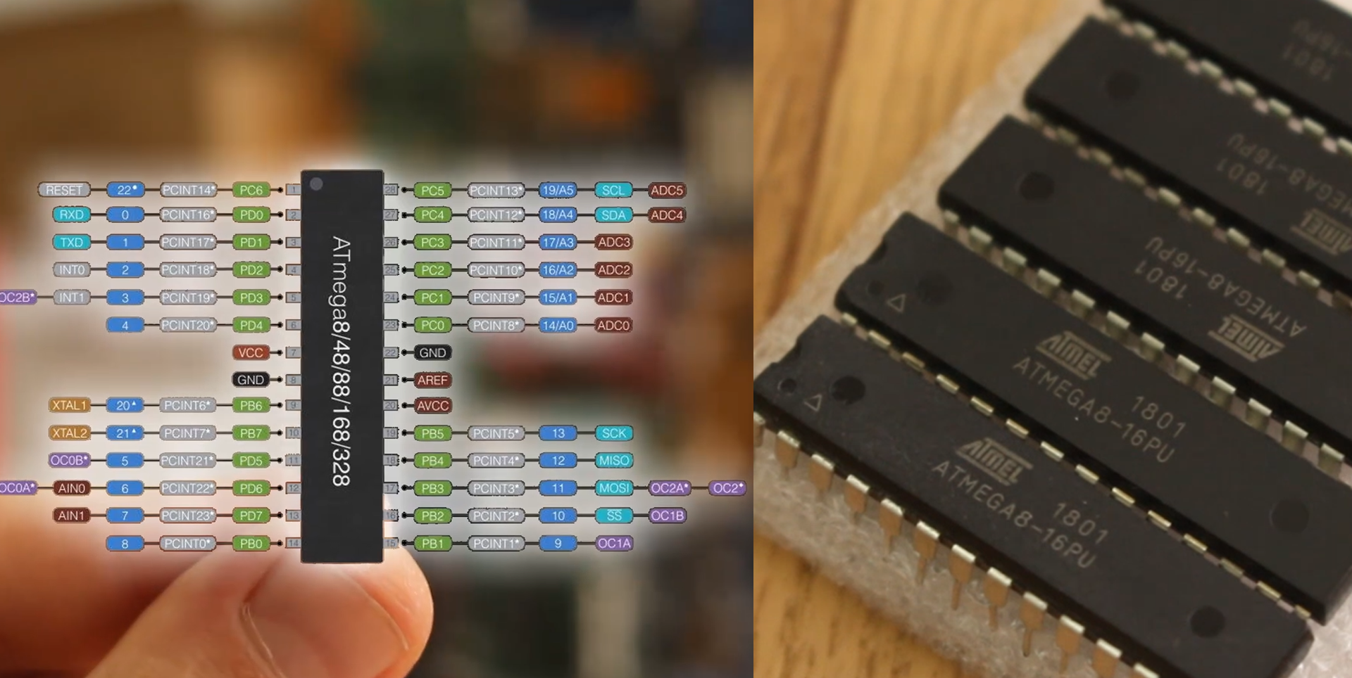
This below is the ATMEGA8 chip. It has 28 pins and this is its pinout. As you can see is pretty much the same as the Atmega328. So why some of you would use this chip instead of the well known 328. Well, probably the price. I’ve bought 10 of this atmega8 chips of only 8 dollars, that’s 80 cents per chip. I’ve also found the SMD version of this chip for only 50 cents.
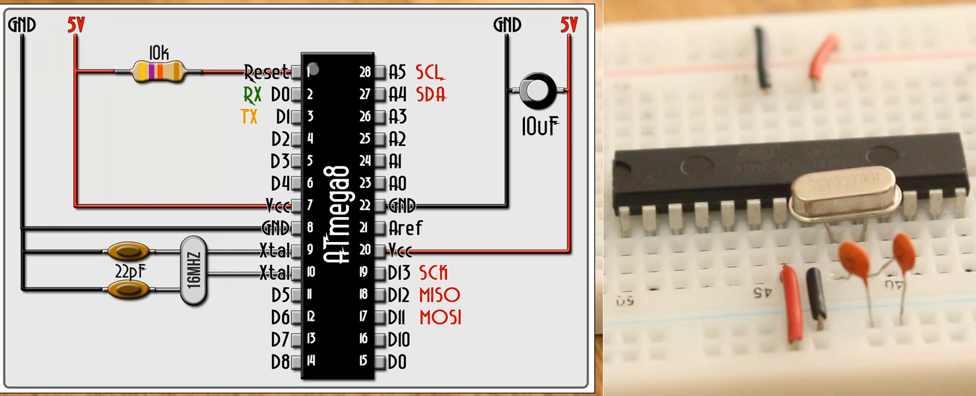
So, how can we use this IC. We have two options. Write the C code, create the hexadecimal file and burn it using the USB ASP programmer and some other software, or use the well know Arduino IDE interface. And we will do just that. But for that, the chip needs a bootloader in order to understand the code we send. So, let’s burn a bootloader. I grab one of my breadboards and place the chip in the middle. Now I make this basic configuration below of this chip using a quartz 16Mhz clock with two 22pf capacitors and a 10k pullup resistor connected to the reset pin which is pin number 1.
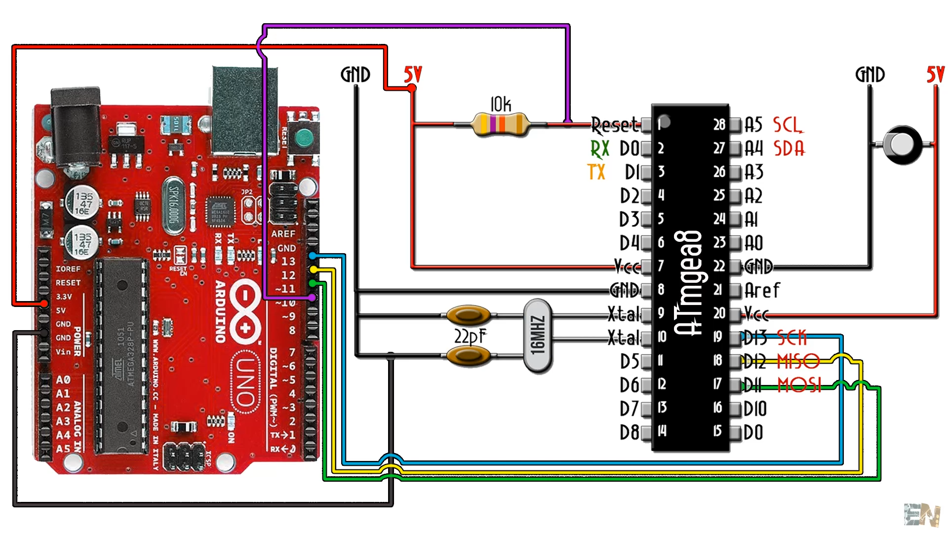
Now we need an ISP programmer. You could use the USBASP like this one, or just use and Arduino UNO. The Arduino board already has SPI port and all we need are the MOSI, MISO and clock pins. We will use Arduino UNO to burn the bootloader since we will use an Optiloader code and that can’t be done with the UASASP.
Connect the Arduino UNO like below to the ATMEGA8. Now connect the USB to the Arduino and open Arduino IDE.
Also, go below and download the OptiLoader code and open it in the Arduino platform.
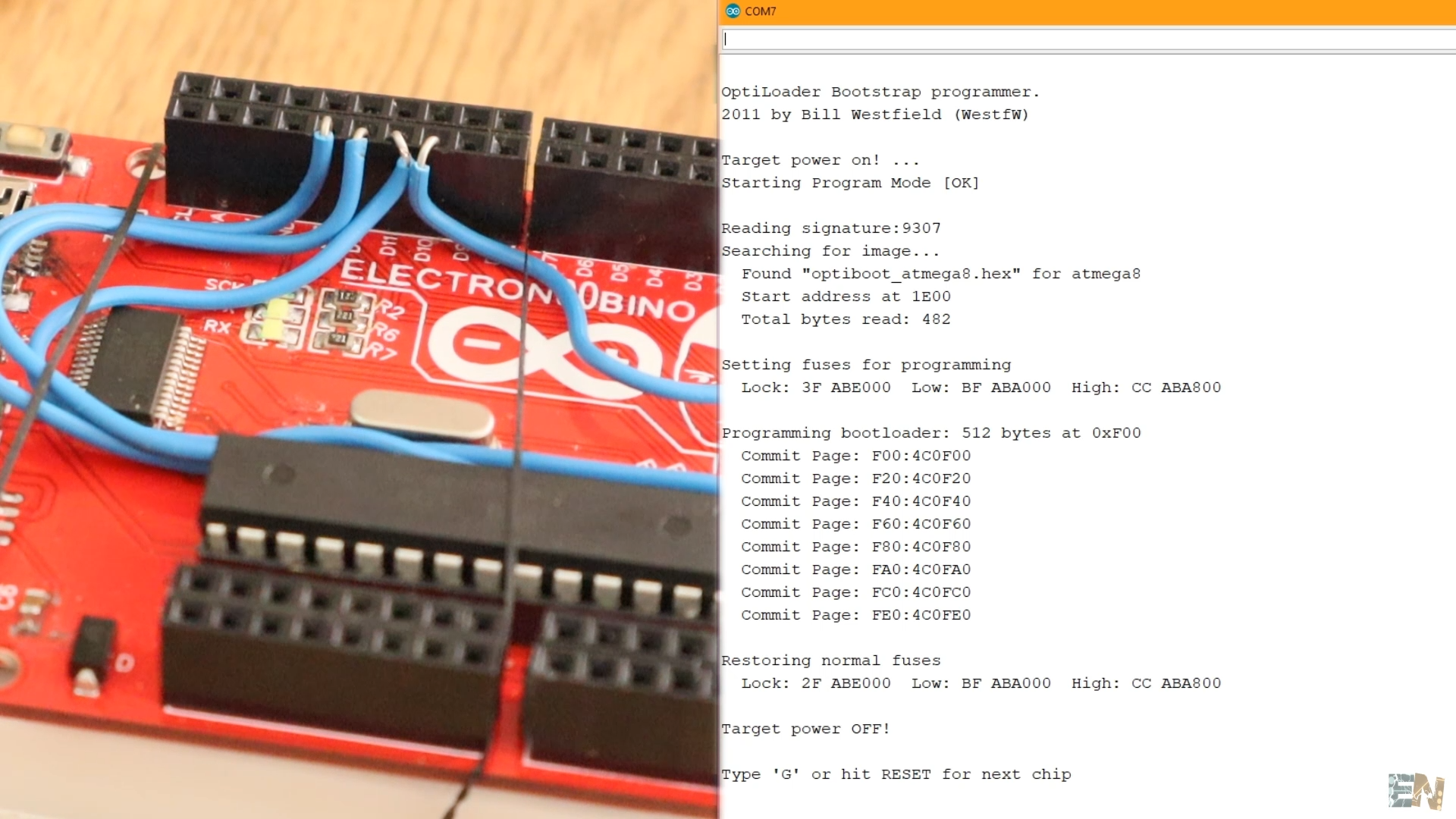
Now make sure you have the connections above between the Arduino UNO and the ATMEGA8 chip and then Upload the code to the Arduino UNO. Once uploaded, open the serial monitor and set the baud rate to 19 thousands and 2 hundred. The bootloader for the ATMEGA8 is now being burned to the chip and you will get these messages below. If you get an error, type G and press enter to try again. That’s it, the chip now has a new bootloader.
Now we have to upload codes. For that we need to install the ATMEGA8 board option to the Arduino IDE and then use an FTDI programmer like this one and with the UART port, upload our sketches.
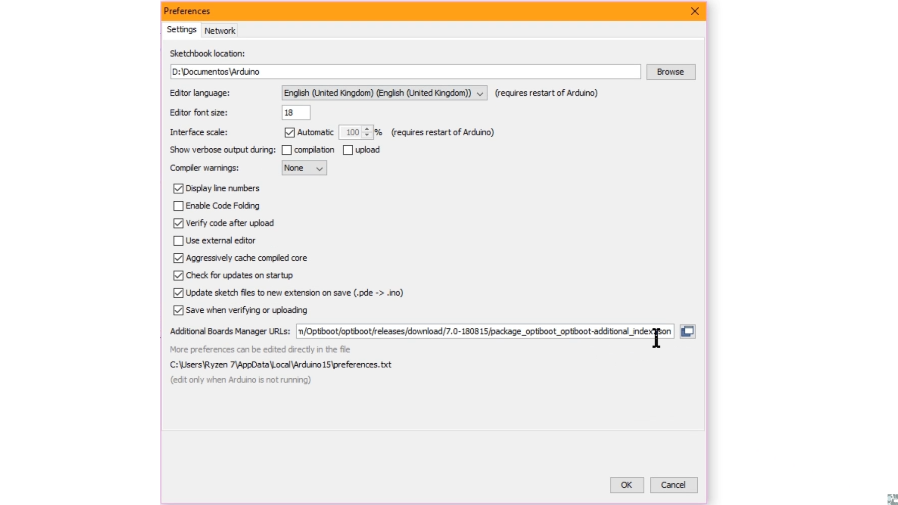
For that copy the json URL from below. Now go to Arduino IDE, File, and select preferences. Now paste the Json URL there as seen in the photo below. If you already have other URLs placed, just ad a comma and then paste the new Json URL. Click Ok, and that will enable the board manager to search for the MiniCore boards.
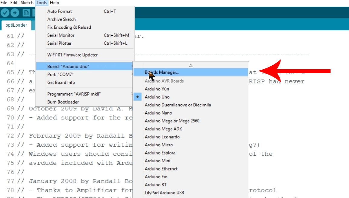
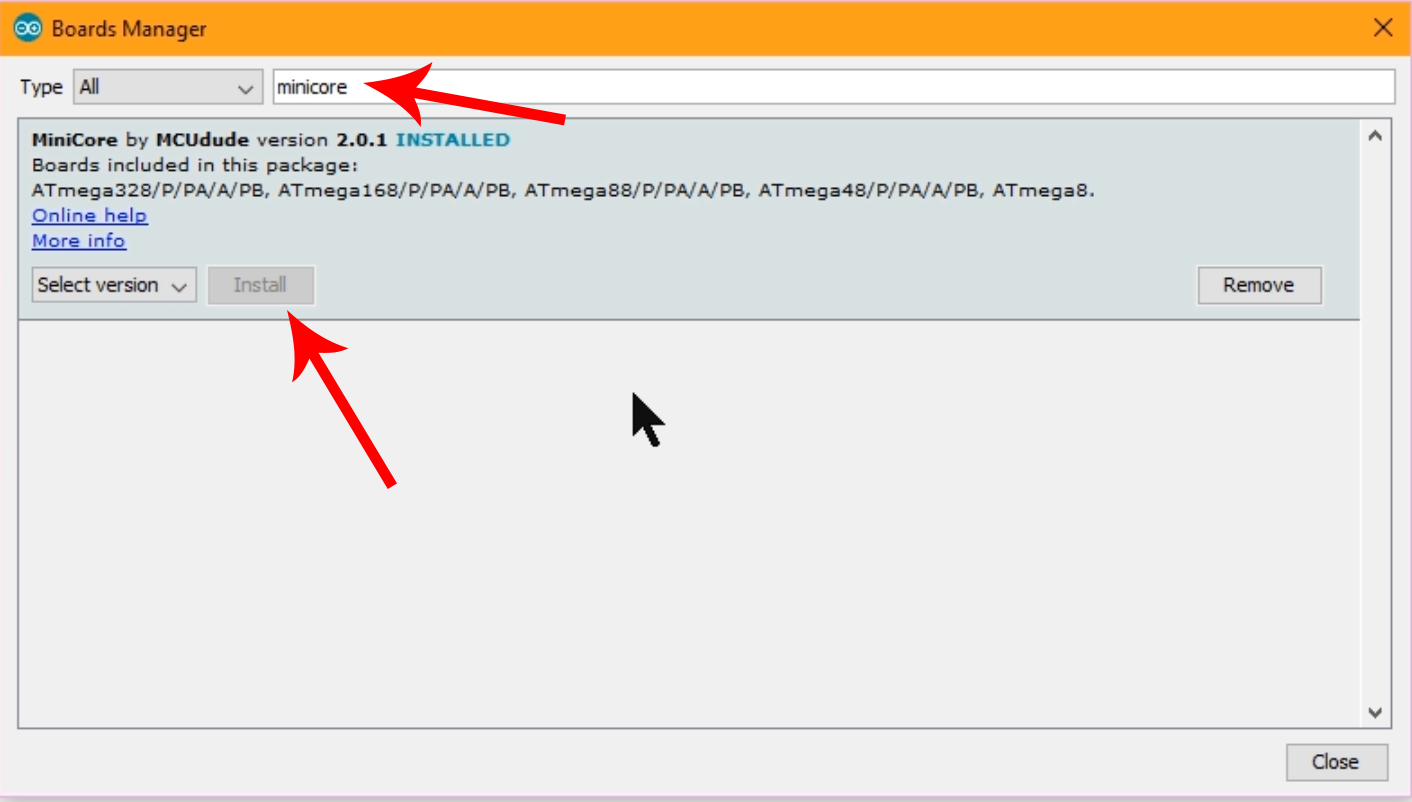
Now go to tools, board and select board manager. Here search for MiniCore and install that boards package. Restart Arduino and not if we go to boards we should have these Atmega boards installed. Select the ATMEGA8 board and let’s upload a blink example. I have now an LED connected to digital pin 10. Let’s make that LED blink.
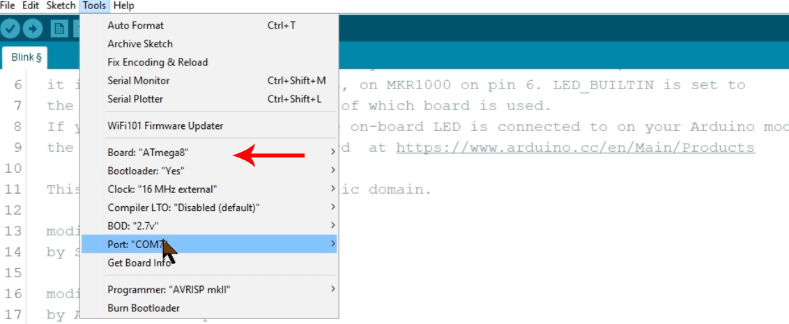
Connect the FTDI programmer like below to the UART port of the ATMEGA8 chip and make sure you add a 100uF capacitor between DTR and reset. I make sure I have the correct board selected (atmega 8) and the correct COM of the programmer and press upload.
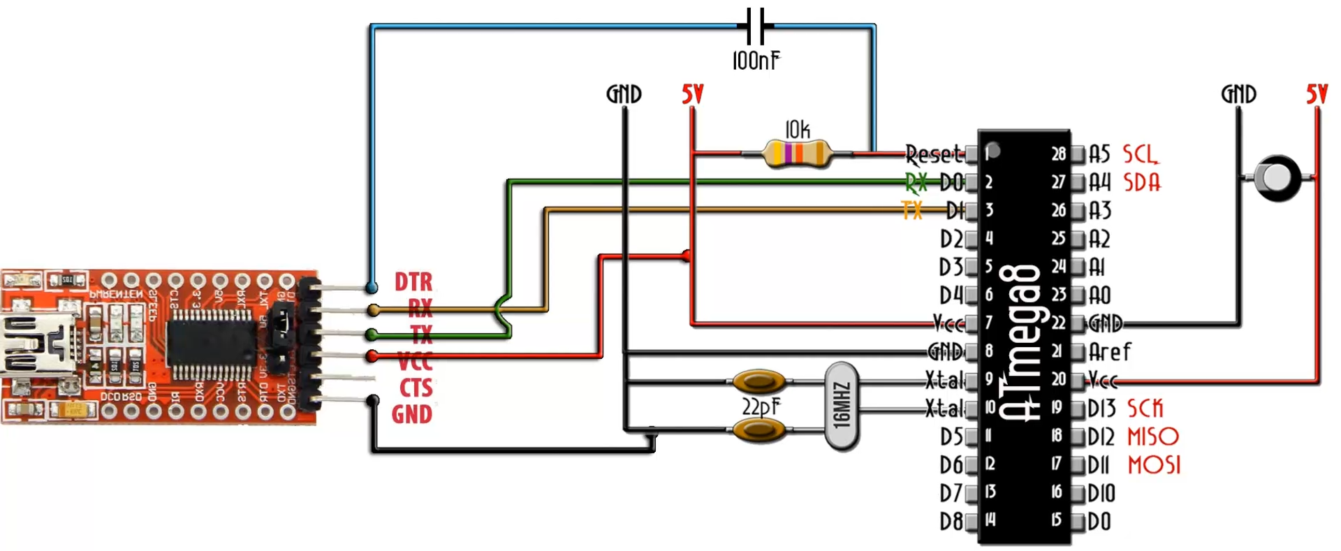
Copy the code below and select the minicore atmega8 board and click upload. Now the LED on digital pin D10 blinks so there you have it. We have succesfully uploaded a code to the ATmega8 microcontroller.
void setup() {
  // initialize digital pin LED_BUILTIN as an output.
  pinMode(10, OUTPUT);
}
// the loop function runs over and over again forever
void loop() {
  digitalWrite(10, HIGH);   // turn the LED on (HIGH is the voltage level)
  delay(1000);                       // wait for a second
  digitalWrite(10, LOW);    // turn the LED off by making the voltage LOW
  delay(1000);                       // wait for a second
}
Since the pinout is compatible, I could even put this chip on an Arduino UNO board and it will work, and I could upload codes using the USB that the board has. So, there you have it. It is not a difficult tutorial but I hope that you will find this useful. Now you could use this chip for yuour projects. In future videos, we will take a look over other AVR microcontrollers or other families as well, maybe PIC or the ESP.