Panel Cookies
FOC Controller - Schematic
11/09/2022 | Views: 23002 | Arduino | by: ELECTRONOOBS      


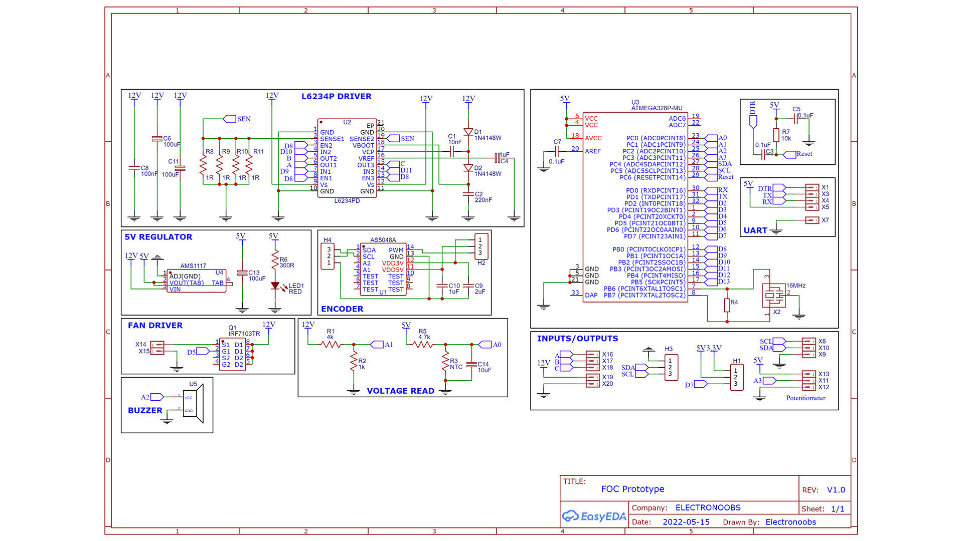
The schematic is quite easy. The basic configuration of the ATmega328 chip. Then, we connect the PWM pins to the driver and from the driver to the brushless motor pads. We create the 5V regulation from 12 to 16V main input. We also have some voltage dividers in order to read the voltage input with the Arduino ADC.


Last tutorials

Laser Power Meter DIY PCB
Measure AC RMS with Arduino
10 Stage Coilgun - Version 2
Tesla Coil on PCB
RLC Transistor Tester PCB with Arduino

ADVERTISERS


>

Affiliate Disclosure

ADVERTISERS


PCBWAY PCB service


Curso Arduino Online nivel Intermedio