Panel Cookies
STM32 Radio Controller - Schematic
20/06/2021 | Views: 31514 | Arduino | by: ELECTRONOOBS      


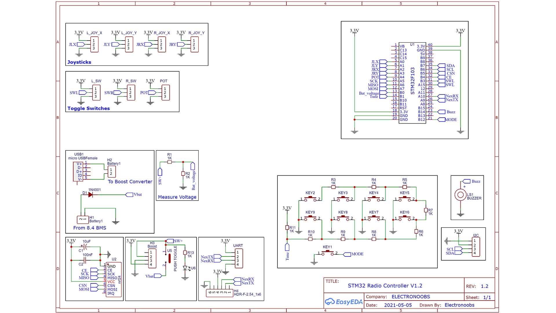
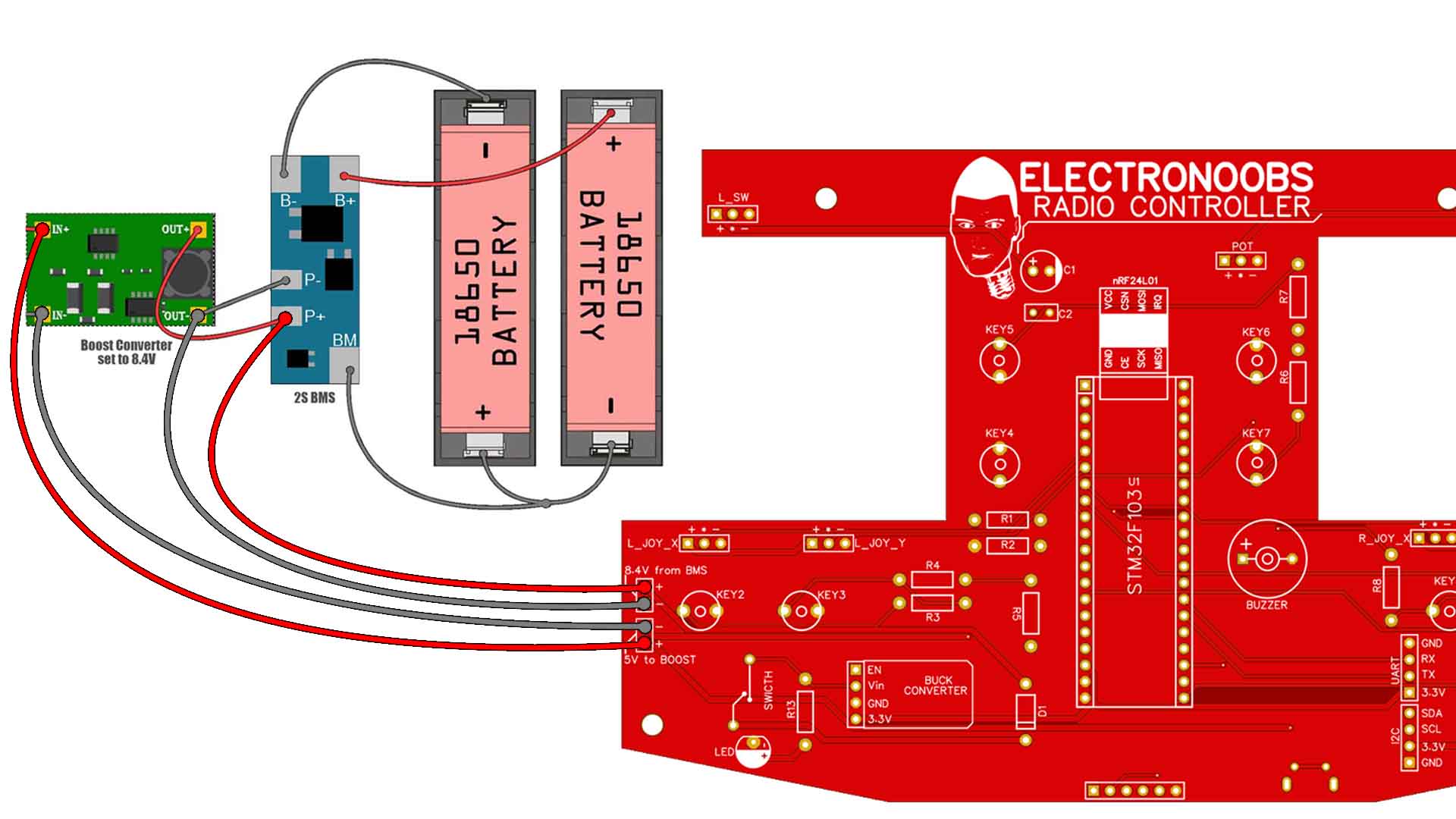
As you can see, comapred with the PCB in the video, the schematic is now changed. We don't have the TP4056 modules anymore. In this case we just have a micro-USB connector for 5V. That is connected to an external boost converter and the converter is connected to the external 2S BMS. The BMS is connected to the batteries as we have seen before and then the 8.4V output is connected back to the PCB. We have some female connectors for that, H1 and H2 on the schematic. Remember, the boost converter and BMS are EXTERNAL to the PCB so connect them as above.


STM32 radio controller schematic

schematic diy STM32 radio controller RC


Last tutorials

Laser Power Meter DIY PCB
Tesla Coil on PCB
RLC Transistor Tester PCB with Arduino
Ferrofluid 3D printed Bluetooth Speaker
10A Bharger/Protection Module

ADVERTISERS


>

Affiliate Disclosure

ADVERTISERS


PCBWAY PCB service


Curso Arduino Online nivel bajo