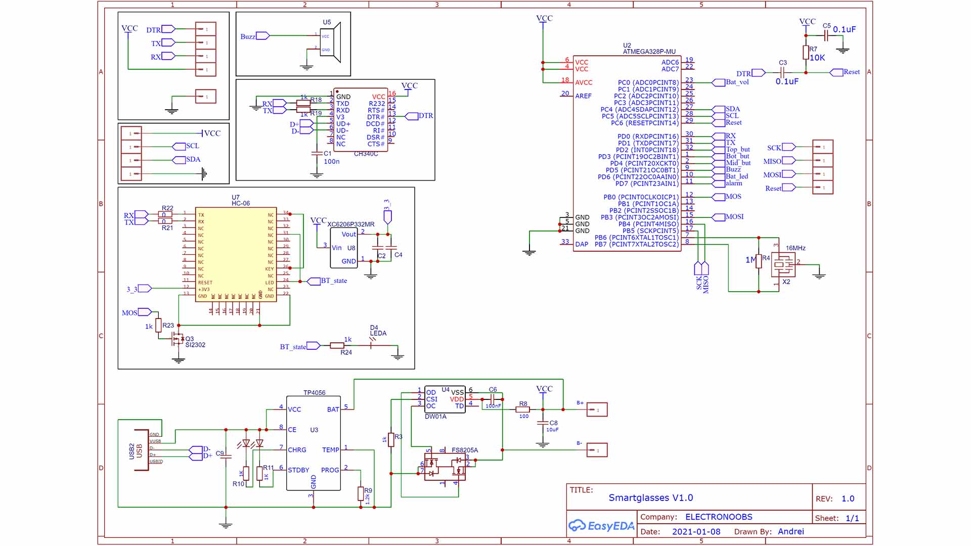
On this PCB we have, the ATmega328 microcontroller, the TP4056 charging IC because this will be portable so it needs a battery. As input, I have a micro-B USB connector. Then we have two sets of pads. Ones are for the OLED display i2c communication and these other pads are for the UART port. And on the back, we have a buzzer for sound notifications and an FTDI programmer, the CH340, so we could program the board with the USB cable. We also have pads for an HC-06 Bluetooth module. And that’s it. I’ve made my schematic and this below is the final version. But I forgot to add a switch, so this PCB would be always on if the battery is connected. I’ll add the switch for the future version. I pass to PCB and decide where to place each component and I try to make the PCB as small as possible.