
 About me
  History
  Let's learn
  Contact us
  Arduino tutorials
 Circuits tutorials
  Robotics tutorials
 Q&A
Q&A Blog
Blog  Arduino
  Circuits
 Robotics
  Modules
  Gadgets
  Printers
  Materials
  3D objects
  3D edit
  Donate
  Reviews
  Advertising


Arduino ANDROID App RGB LED strip control
This will be an awesome tutorial. We will see how to create an App in app inventor with some buttons for each color. Send data with our smartphone to the arduino using a bluetooth connections between the android smartphone and a HC06 bluetooth module. With the receive data, we decide which color of the RGB strip to activate. In order to use high current we will use some transistors between the RGB strip and the arduino.
Material
1 x Arduino (NANO or UNO)
1 x Bluetooth module HC06
3 x BD681 NPN transistors or (BD140 PNP)
3 x 1k ohm resistors
1 x RGB LED strip
1 x 12V 1.5A or more DC transformer
Drilled PCB, connectors, solder,etc...
Schematic
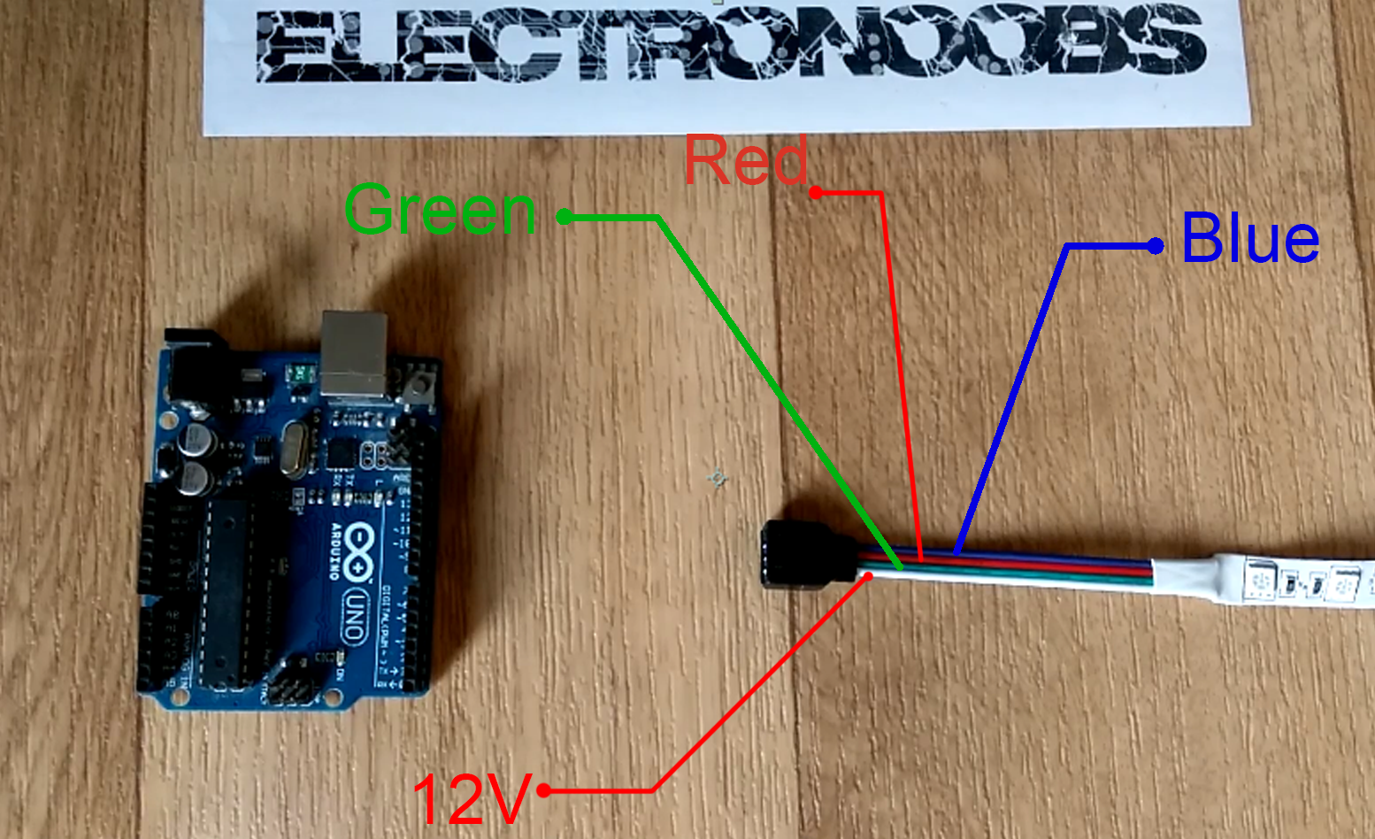
First let's examine the LED strip input. It has 4 wires. The first one, usually white, is the positive 12V input. The other 3 wires are the red, green and blue signal wires. In order to create a broad variety of colors we should give more or less brightness to each of this 3 basic colors. To do that we shoould apply a PWM signal to this color pins. If the white pin is already connected to a positive 12V votage, in order to close the circuit, the RGB output pins should be modulated toward ground.
The problem is that Arduino digital outputs can'y supply more than 200mA and this strip at full brightness could draw more than 1A. For that we have to put something between the Arduino PWM signal and the LED strip. To do this we have two options. Use a NPN transistor twith the emmiter pin connected to ground aor a PNP transistor with the emitter pin connected to the RGB output pins. This will allow current to flow from the 12V input, toward ground and at the same time through the LEDs makeing them glow.
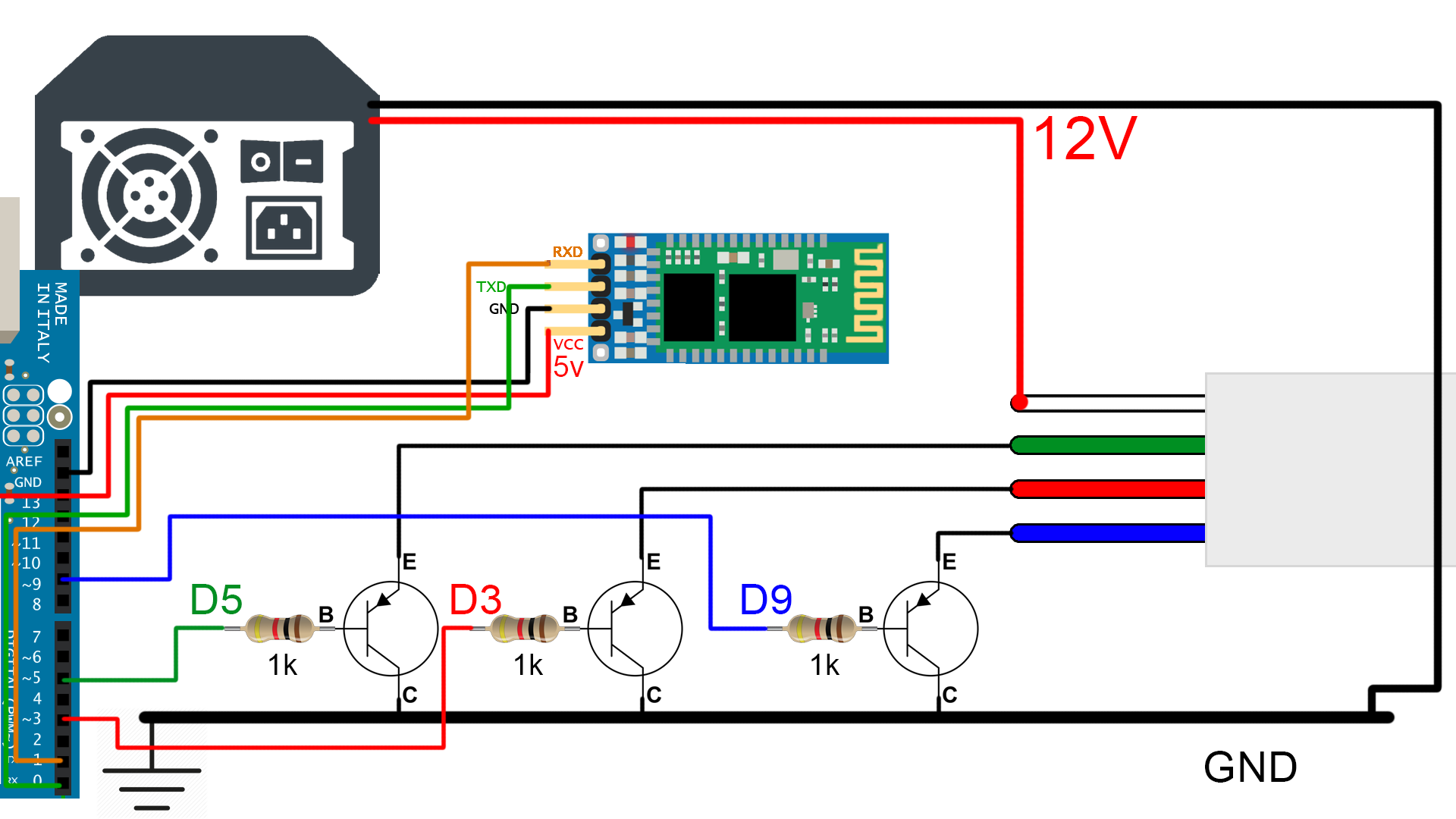
NPN schematic
If we use NPN transistors the full brightness of each color will be achived with a maximum PWM width and for PNP transistors just the oposite, with a 0 PWM width soi be careful.

Connect theHC06 bluetooth Vcc pins to the 5V output from the Arduino. Also share ground between the module and the microcontroller. Connect the Rx pitn to the Tx and the Tx to the Rx like in any other UART connection.
PNP schematic
If we use PNP transistors the full brightness of each color will be achived with a minimum PWM width so be careful to change the code if needed.
Connect theHC06 bluetooth Vcc pins to the 5V output from the Arduino. Also share ground between the module and the microcontroller. Connect the Rx pitn to the Tx and the Tx to the Rx like in any other UART connection.