Panel Cookies
Electronic load - SCHEMATIC 2
27/06/2020 | Views: 46669 | Arduino | by: ELECTRONOOBS      


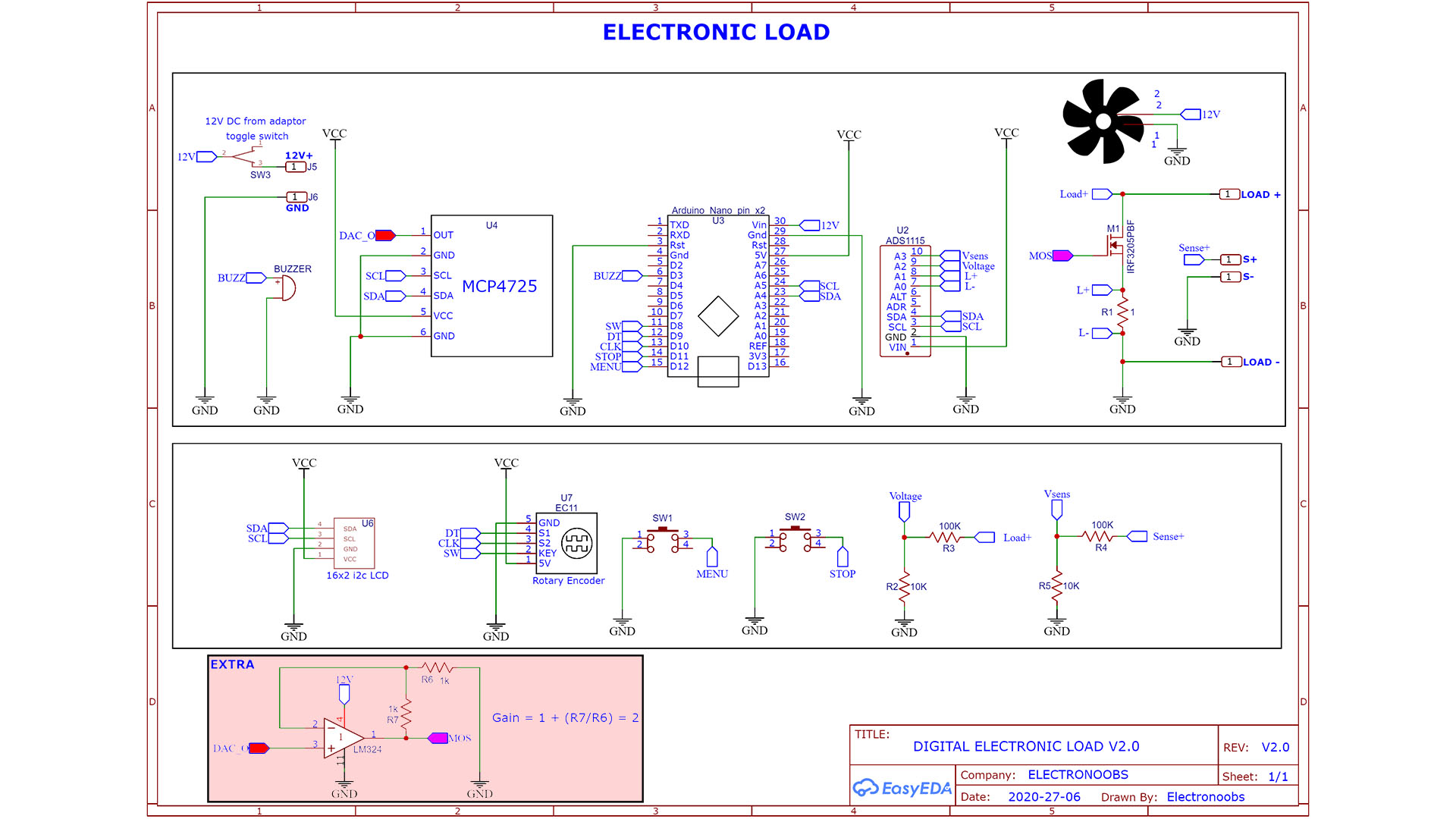
If you want the controller to go more than 2.1A, you will need more voltage at the MOSFET gate then 5V that the DAC could give. For that use this second schematic below with an OPAMP between the DAC and the MOSFET gate. The gain is 2 so the output from the OPAMP will eb around 5V * 2 so around 10V which should be enough to go up to 5A or more. See the other schematic here without the OPWMP.


Arduino digital constant power controller schematic


Last tutorials

All about Arduino PWM frequencies
Smallest ESC based on ARDUINO
Debug Arduino and ESP with PlatformIO
Homemade Best Two Hand Multimeter with Arduino
Homemade Baby White Noise Generator

ADVERTISERS


Affiliate Disclosure

ADVERTISERS


PCBWAY PCB service


Curso Arduino Online nivel Intermedio