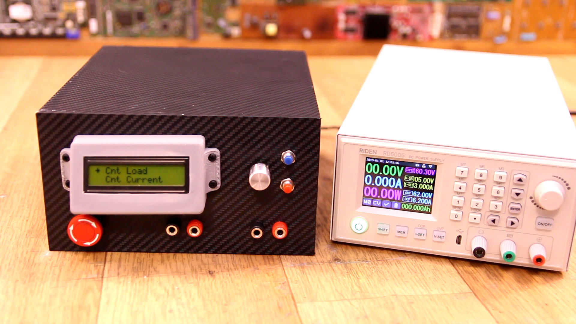
In this tutorial I show you how I've build a homemade electronic load with Arduino, an LCD, rotary encoder for the menu and a power MSOFET for load control. It also has a good cooling system so it could handle high loads. See how to make the circuit, the case, connect everything, see the code I've used and which modules and make the same project. Hope you like it. If this tutorial helps you, consider supporting my work.
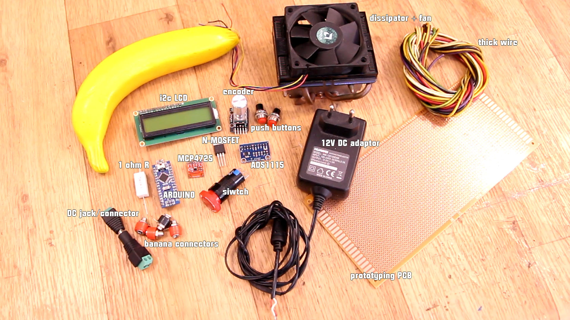
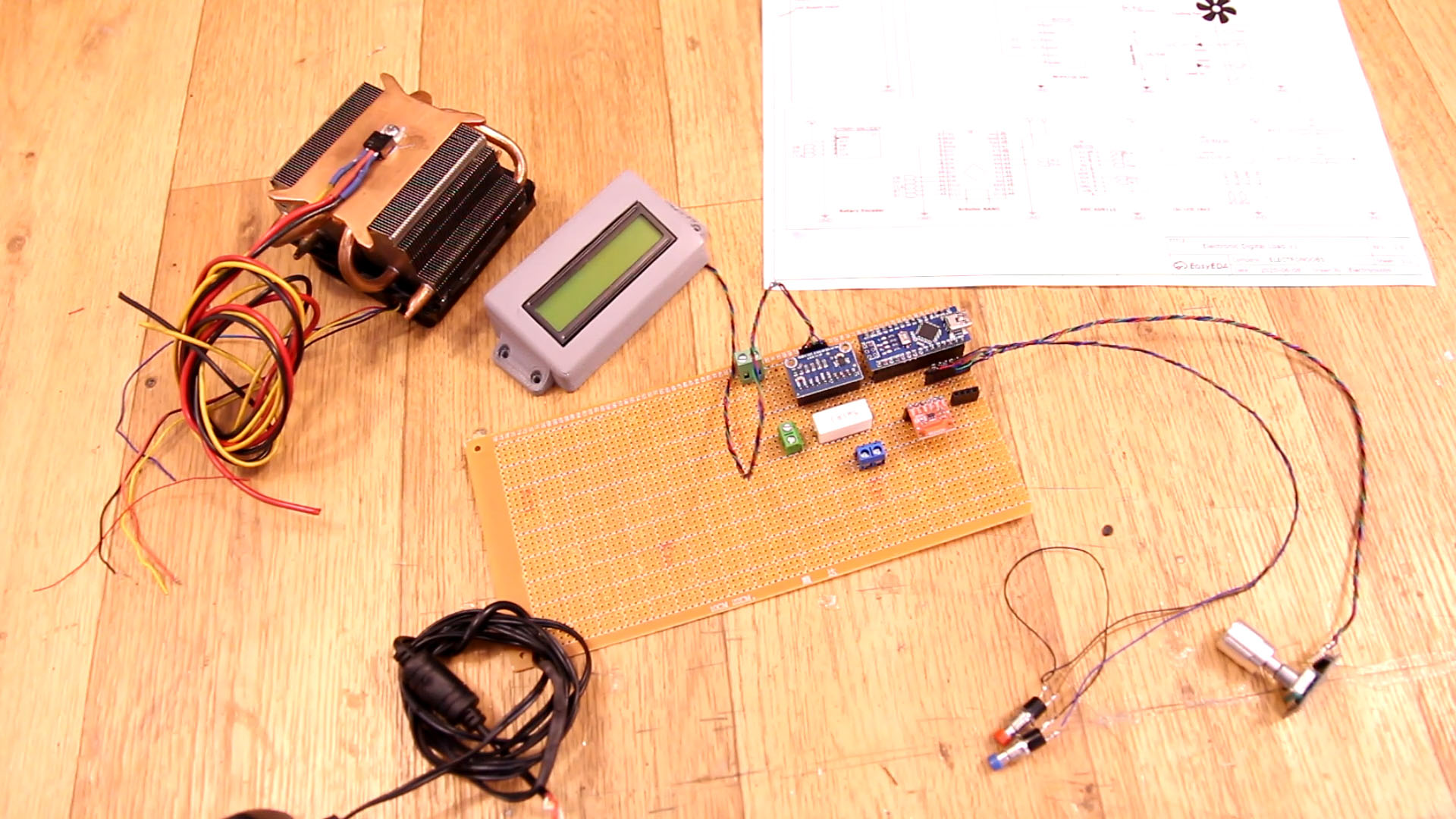
This are all the electronics we need for this project. You also have a list with some other parts we need such as plywood, the cooler, the 3DF printed fan covers and screws. The electronics are easy to use. All modules are using i2c communication. For the heat dissipator I've used a PC cooler and works great. You will need thin wire for 5V connections but thick wire for the MOSFET and power lines.
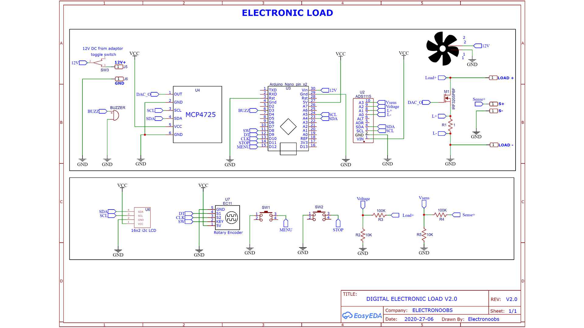
• Let's talk about the schematic. Is important and you might need to adapt it to your needs. First of all, 12V from the DC adaptor is connected to a toggle switch and then to the Arduin o Vin pin and the fan so when we toggle the switch, everything is powered on. The NANO has a 5V regulator and that will be our Vcc. Supply all modules to Vcc and GND and connect the SDA and SCL pins from the Arduino to all i2c modules (ADC, DAC and LCD).
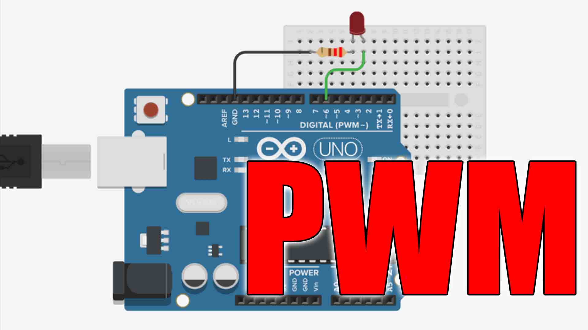
• Connect the encoder to Vcc, GND and the 3 pins to digital pins D8, D9 and D10 of the Arduino. Connect the push buttons to pins D11 and D12. Also connect the buzzer to D3 for PWM signal for tones.
• About the voltage divider. Please read the code and the next parts of the tutorials. I've used 10K and 100K but those are not exactly these values so we need to adapt the multiplier in the code. Read the code.
• To read the current I use a 1ohm shunt. We read the voltage on this load in differential mode with the ADC. Again, this resistor is not exaclty 1ohm, so the multiplier will be adapted in the code. Read that part later. Connect the DAC output to the gate of the MOSFET. Load+, Load-, S+ and S- are the banana connectors we haev on the front panel. That's it.
If you want the controller to go more than 2.1A, you will need more voltage at the MOSFET gate then 5V that the DAC could give. For that use this second schematic with an OPAMP between the DAC and the MOSFET gate.
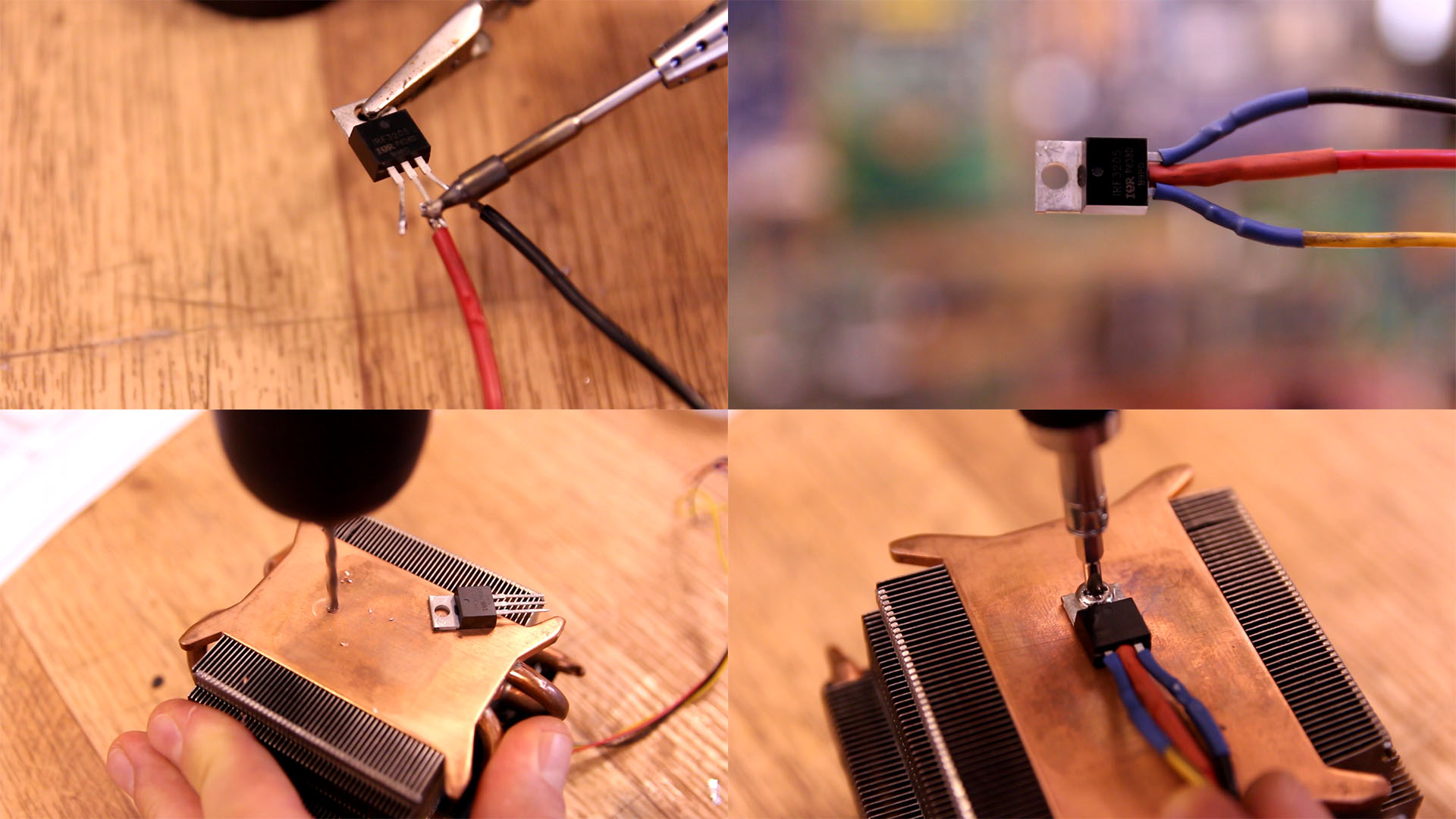
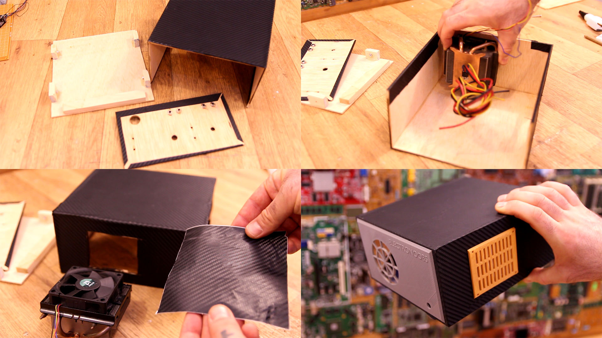
Ok, get the MOSFET and solder thick wires to the drain, gate and source. Add shrinking tubes for insulation. Then measure the position and make a hole in the heat dissipator. Add some thermal paste and screw in place the MOSFET. Now you should have the entire power block with 3 wires.
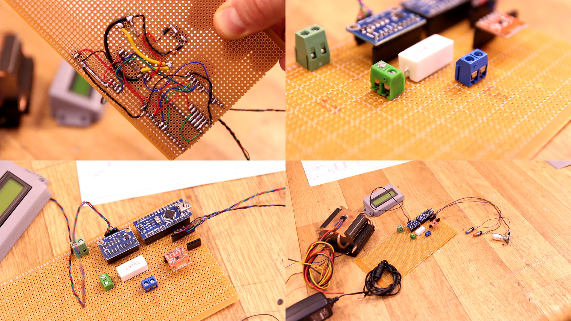
On a prototyping PCB, solder all the components. I use thin wires for the low power connections such as 5V for the modules, i2c connections and push buttons. For the path from input through the load and to the MOSFET use thick wires connections. Also, make the connection from the ADC0 and ADC1 of the ADS1115 to the terminals of the 1ohm resistor very short. The longer these connections are, more voltage drop there will be on the load, and we need to read the drop exactly on the LOAD. For the push buttons, LCD and encoder, we add long thin wires for future connection to the PCB with some male-female pins. For power connections add some screw terminals if you have.
Below you can see the connections on the bottom side of the PCB. As you can see I've used thick wire for the pwoer path so it could handle high current. I've also filled with solder some connections for the same reason. I've placed female pins so I could later connect the LCD, encoder and those 2 push buttons. Now we can even make a test and then make the case.
I've used plywood and made a simple case. I start with 4 walls, the top one, sides and the back wall. I measure where to fit the coolder fan on the back panel. I then cut a hole in taht back panel for the fan and another one on the right side for air flow. Then I cover the enirte case with carbon fiber texture vinyl so it will look better. I then 3D printe the fan covers. Download those from here. Using super glue I glue the covers in place.
Then I glue 4 wood blocks on the bottom part adn add a M3 nut. These will be used to close the case when is finished using M3 screws. I then make the front panel and wrap it in carbon fiber vinyl. I print the LCD support and place it inside. Then I decide where to palce each component. I make holes and add all the buttons, LCD, encoder and connectors. I then glue the fron pannel to the case and make connections to the PCB. Secure the PCb inside with glue.
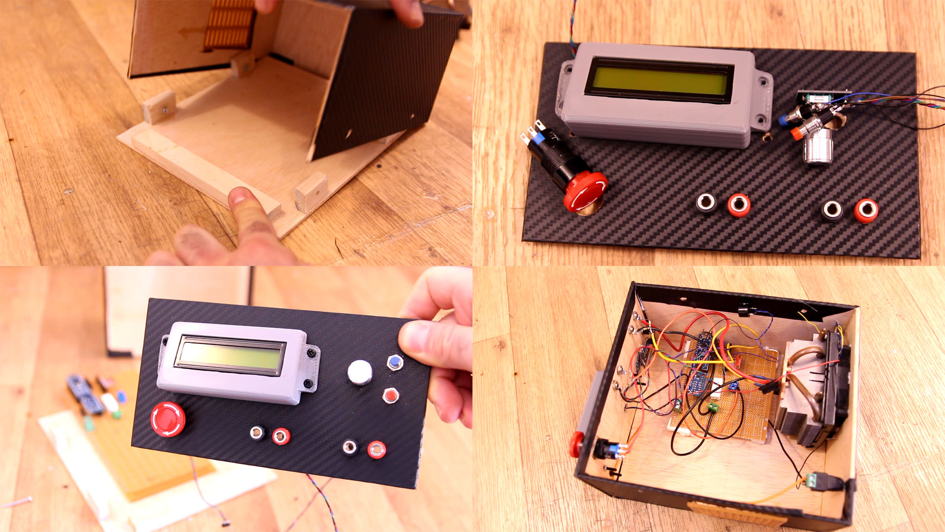
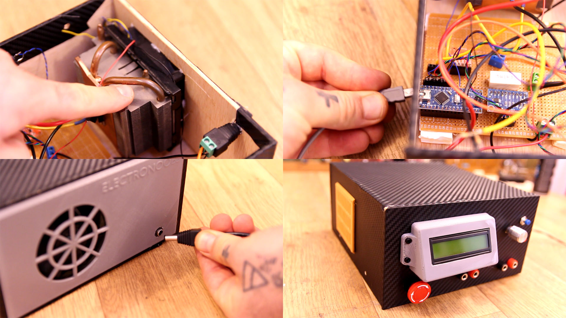
The fan is glued in place on the back panel. I make a hole on the side and make sure the Arduino USB connector will be in front of that hole so I can program the chip with a USB cable. The main 12V DC connector has a hole on the back so we can connect power here. That's it. Close the case with screws and we can uplaod the code.
Go below and download the code. You will need the libraries for the LCD, the ADS1115 and the MCP4725 modules and you can download those libraries from the next link as well. You will also need the BusIO library so install that with the library manager of Arduino IDE. Read the code for more details, especially the multiplier part. Compile and upload and then test the controller.
This part is important. You see, when you sue the ADS1115, to pass from bit values (0 to 65000), we use a multiplier. By default that is "0.185mv" or "0.000185V". In the code, to measure current, we make a differential measurement of the voltage on the "1ohm" load. Since the load is 1ohm, that will give us DIRECTLY the current value since "I = V/R" and R is 1. BUT!!! The resistor is not exactly 1ohm, so in my case I've adapted the multiplier to 0.0001827. You might need to adjust this variable to other values till you get good readings, so while measuring the value with an external multimeter at the same time, adjust this variable till you get good results.
The same goes here. But in this case, the voltage read is from a voltage divider. You see, the ADS1115 can only measure up to 5V. If the input is higer it will get damaged. So, for that btween the ADS1115 and the main input I've used a 10K and 100K divider and that will equal to a divider of 0.0909090. So, now the multiplier is 0.000185 / 0.0909090 = 0.002035. Now these resistor values are not perfect neighter so we don't have exactly 10K and 100K, that's why my multiplier for voltage read is 0.0020645. Just do the same, measure the voltage on the LCD screen and also with an external multimiter and adjust this value till you get good results. I've measure the resistors but that's not enough. We need precise values.
const float multiplier = 0.0001827;     //Multiplier used for "current" read between ADC0 and ADC1 of the ADS1115
/////////////////////////////////////////////////////////////////////////////////////////////////////////////////////////////////////////
const float multiplier_A2 = 0.0020645;   //Multiplier for voltage read from the 10K/100K divider
I hope that you like this tutorial. If you consider supporting my work, buy my PCBs on my shop, or maybe consider supporting me on PATREON or if you want, make a PayPal donation. Thank you very much.
• Something to have in mind. In this version, I'm not using the sense probes. The code was too slow if I read the input voltage and sense voltage at the same time but I'll try to add this feature in a future version.
• Also, the current control is made by changing the voltage at the MOSFET gate. This control should be PID for very good results but the ADC read and DAC write are slowing the code so much, that a good PID was not working. So, instead of PID I've made a "manual control" and I decide the proportional value dependind on the error range. Below you can see an example. If the error is very big, bigger than 80% of the setpoint, then the DAC output will change in steps io 300 from a total of 4069. If the error is 60% of the setpoint in steps of 170 and so on. If the error is small, the steps are jsut 1 from a toral of 4069 so we have good control. This works but is not perfect.
   if (error > (mW_setpoint*0.8))
    {
      if(mW_setpoint > power_read){
        dac_value = dac_value + 300;
      }

      if(mW_setpoint < power_read){
        dac_value = dac_value - 300;
      }
    }


    else if (error > (mW_setpoint*0.6))
    {
      if(mW_setpoint > power_read){
        dac_value = dac_value + 170;
      }

      if(mW_setpoint < power_read){
        dac_value = dac_value - 170;
      }
    }


    else if (error > (mW_setpoint*0.4))
    {
      if(mW_setpoint > power_read){
        dac_value = dac_value + 120;
      }

      if(mW_setpoint < power_read){
        dac_value = dac_value - 120;
      }
    }
    ...
I hope that you like this tutorial. If you consider supporting my work, buy my PCBs on my shop, or maybe consider supporting me on PATREON or if you want, make a PayPal donation. Thank you very much.