Arduino register control, timers and interruptions
Arduino register format and control

There are many types of registers like adress register, control, flags, etc. Here is a full list with all the register types. In digital electronics, especially computing, hardware registers are circuits typically composed of flip flops, often with many characteristics similar to memory. In electronics, a flip-flop or latch is a circuit that has two stable states and can be used to store state information, in this case a logic "0" or "1". Registers are normally measured by the number of bits they can hold, for example, an "8-bit register" or a "32-bit register". In the photo above we can see an 8 bit register. Each case represents a bit. LSB or LAST significant bit represents the lower values of the register and the MSB or most significant bit the higher. As you can see the LSB has a lower values than the MSB. If we want to convert this register binary value to decimal we would have to make the sum of each bit as we can see in the photo above. If we have a logic "1" we have to raise the noumber "2" to the power representing the bit position or a 0 when the bit is a "0" logic and make the sum of all of them. In this case the register has a 22 value in decimal format.
So we could asignate a task to each bit. In this way we can store information about any thing in our microcontroller. For examble let's take a look at the ATMEGA328 datasheet, which is the microchip that the Arduino UNO uses. We will talk a bit about the registers that control the digital outputs/inputs. We open the datasheet PDF and open the search bar. Type in DDRD which is the direction register of the D port of the Atmega328 chip. You see, to each digital port is assigned a name. To know to which port is each pin assigned just google up a picture of the ATMEGA328 pin layout or just search it in the datasheet. Se we will work with the port D which includes the digital pins D2 to D7. In the photo below we can see the port name with yellow and the corespondent digital input/output pin with pink. So for example let's take the PD2 which is the pin "2" of the "D" port.
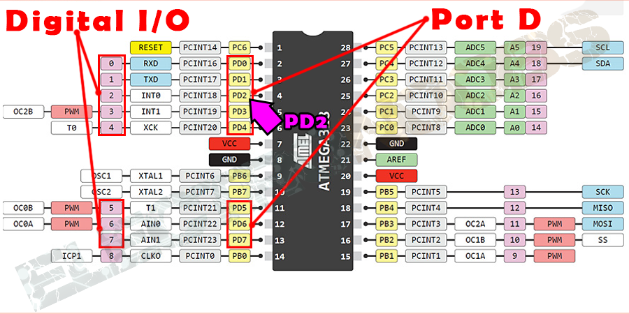
Se we've chosen the PD2. Let's take a look at the datasheet of the ATMEGA328. Search for DDRD. You will see something like in the photo below. Each register dose its job. For example the DDRD rergister will set the direction of each pin to output or input depending on the value of the bit coresponding to that pin. So if we want to set our pin as an OUTPUT pin we just have to put a "1" in the 3rd direction of the DDRD register. If we want it as INPUT just put a "0". We can see that the initial values is set to "0" so all the pins are initially set as INPUTS.
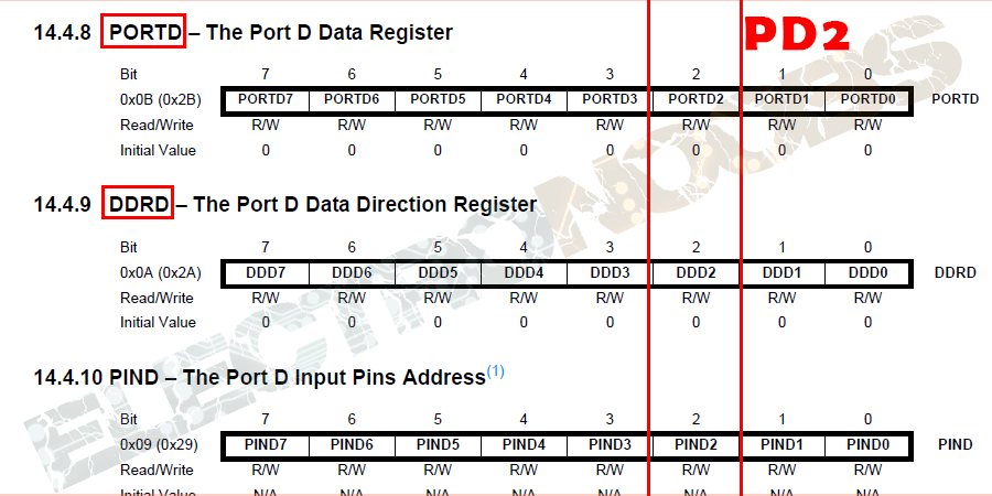
Now if we want to se the pin to HIGH or LOW we have to change the values in the PORTD register which is in charge of the data output of each pin. To set the figital pin D2 to HIGH just put a "1" in the 3rd position of this register or a "0" for a LOW state. In order to change the values of this register we will use some LOGIC OPERATORS. We use "|" which is an "OR" operator to put ones and a "&" which is an "AND" operator to put zeros. So why we use one to put 0 and the other to put 1? The answer is simple. An AND operation between any values of the register and a "0" will always give the 0 result. So if we want to put a "1" using the AND operator and the register already has a "0" in that position we would have a 0&1 and the result would be still a "0" so we haven't done our job. But the result of an OR operation will always give a 1 if there is a 1 in the operation. In the photo below we can see the truht table of each of this two operations where A is one operator, B is the seacond and X is the result.
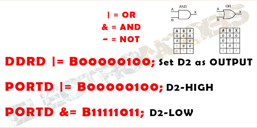
Ok so we want to put a "1" in the 3rd position of the DDRD register without affecting the other positions. That's why we use an OR operation. In arduino we use that the DDRD register is iqual to OR operation with the B00000100 balue using "|=". This operation will put a "1" in the DDRD register in the place where the seacond operator has a 1 and leave all the other position unchanged. To set to high the pin we put a "1" in the 3rd position of the data register of the port D or a "0" to set it to low. As I said we use the AND operator to put zeros. You can see taht only the 3rd bit is a zero, the rest are all ones in order to not change the other values of the register. We only want to change the 3rd position. In order to obtain the 11111011 value we could also use the NOT operator "~" which would reverse the logic values of the opoerator like this: ~00000100 = 11111011.
So, in resume, always check the datasheet of the microchip and study all its values. Use the register to change ports, timers, or store something on the flsh memory. Make sure to what each register coresponds. Use the logic operators to change values.
Difference between function use or register control
A) digitalWrite
The difference is always speed. So my Arduino UNO works as a 16MHz speed. So if I set a pin to HIGH and just fraction of time after to LOW I should have a very small pulse but using the
Upload the next code to the arduino and connect the osciloscope probe to pin D2.
void setup() {
  pinMode(2, OUTPUT);

}

void loop() {
  digitalWrite(2,HIGH);
  digitalWrite(2,LOW);
  delay(100);

}
B) register contrrol
Now let's do the same using register control. Set the pin D2 as output puting a "1" on the 3rd position of the DDRD register. Then make a HIGH to LOW switch using the PORTD register. Copy the code below and upload it to the arduino and once again connect the probe to pin D2 and observe.
void setup() {
  DDRD |= B00000100; //Set the D2 as OUTPUT

}

void loop() {
  PORTD |= B00000100; // Pin D2 to HIGH
  PORTD &= B11111011; // Pin D2 to LOW
  delay(100);

}
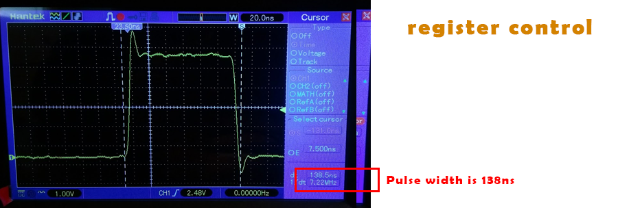
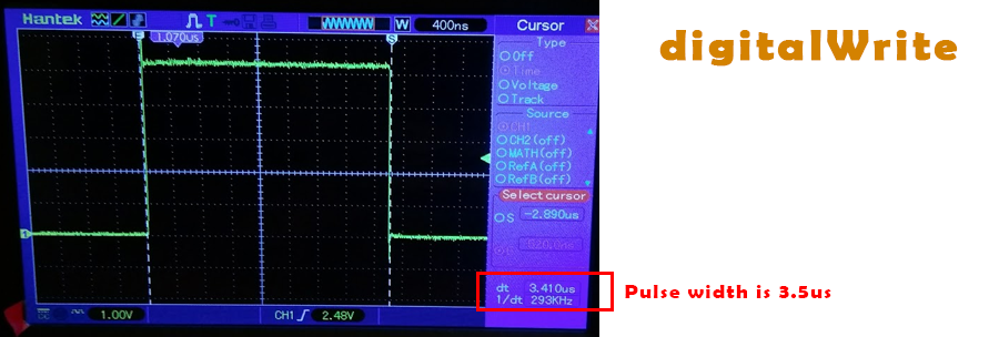
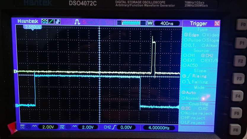
As you can see the difference is huge. Even if we work at a 16MHz speed, digital write function takes about 3us to create a pulse. That gives us a maximum frequency of 333KHz which is about 50 times slower than 16MHz. But, if we use register control the pulse width reduces to just 130ns so a frequency of 7.2MHz. So using register control we could work 20 times faster. In the photo below we can see the huge time difference between the two ways to make a pulse.
Timers control
A) set a timer
A lot of Arduino functions use timers, like the delay() function. To create a delay the microchip uses an internal timer. Each pulse of this timer creates an interruption each defined time, lets say one microseacond, which means that the frequency of the timer is 1/1us = 1MHz. Each time an interuption is made, the delay function increments a value. When this value reaches the desired delay value, the function exit the loop and finis the delay. But programming the arduino you don't even notice all this steps. Other functions of the arduino are using timers, such as millis() and micros() and delayMicroseconds(). The PWM function analogWrite() uses timers, as do the tone() and the noTone() functions. And the Servo library uses timers and interrupts.
What is a timer?
A timer and to be more precise a timer / counter is a piece of hardware built into the controller. It is like a clock, and can be used to measure time events. The timer can be programmed by some special registers that we will talk about later. You can configure the prescaler for the timer, or the mode of operation and many other things.
The controller of the Arduino is the Atmel AVR ATMega 168 or ATmega328. These chips are pin compatible and only differ in the size of internal memory. Both have 3 timers, called timer0, timer1 and timer2. Timer0 and timer2 are 8bit timers, where timer1 is a 16bit timer. The most important difference between 8bit and 16bit timer is the timer resolution. 8bits means 256 values where 16bit means 65536 values for higher resolution or longer count.
All timers depend on the system clock of your Arduino system. Normally the system clock is 16MHz, but for the Arduino Pro 3.3V it is 8Mhz. So be careful when writing your own timer functions.
The timer hardware can be configured with some special timer registers. In the Arduino firmware all timers were configured to a 1kHz frequency and interrupts are generally enabled.
Timer settings
You can change the Timer behaviour through the timer register. The most important timer registers are:
TCCRx - Timer/Counter Control Register. The prescaler can be configured here.
TCNTx - Timer/Counter Register. The actual timer value is stored here.
OCRx - Output Compare Register
ICRx - Input Capture Register (only for 16bit timer)
TIMSKx - Timer/Counter Interrupt Mask Register. To enable/disable timer interrupts.
TIFRx - Timer/Counter Interrupt Flag Register. Indicates a pending timer interrupt.
Clock select and timer frequency
Different clock sources can be selected for each timer independently. To calculate the timer frequency (for example 2Hz using timer1) you will need:
CPU frequency 16Mhz for Arduino
maximum timer counter value (256 for 8bit, 65536 for 16bit timer)
Divide CPU frequency through the chosen prescaler (16000000 / 256 = 62500)
Divide result through the desired frequency (62500 / 2Hz = 31250)
Verify the result against the maximum timer counter value (31250 < 65536 success) if fail, choose bigger prescaler.
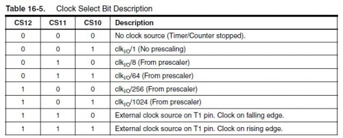
There are a lot more registers that we could change for each timer. The next steo that we are going to talk about are interruptions. We will have to set this timer registers to perform the exact interruptions that we want.
A) Timer interruption "ISR"
A) Create a PWM using ISR and register control
More tutorials:

 About me
  History
  Let's learn
  Contact us
  Arduino tutorials
 Circuits tutorials
  Robotics tutorials
 Q&A
Q&A Blog
Blog  Arduino
  Circuits
 Robotics
  Modules
  Gadgets
  Printers
  Materials
  3D objects
  3D edit
  Donate
  Reviews
  Advertising


