How are these induction heaters work? We will look over the circuit and explain step by step how the oscillating signal is created, how current is induced and how the metal will get hot. Finally we use that schematic and mount a homemade version and see if it works to heat up some metals. So let's see...
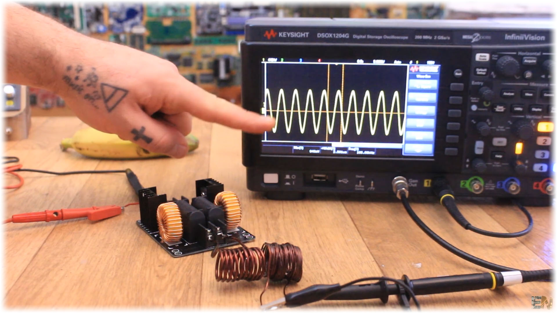
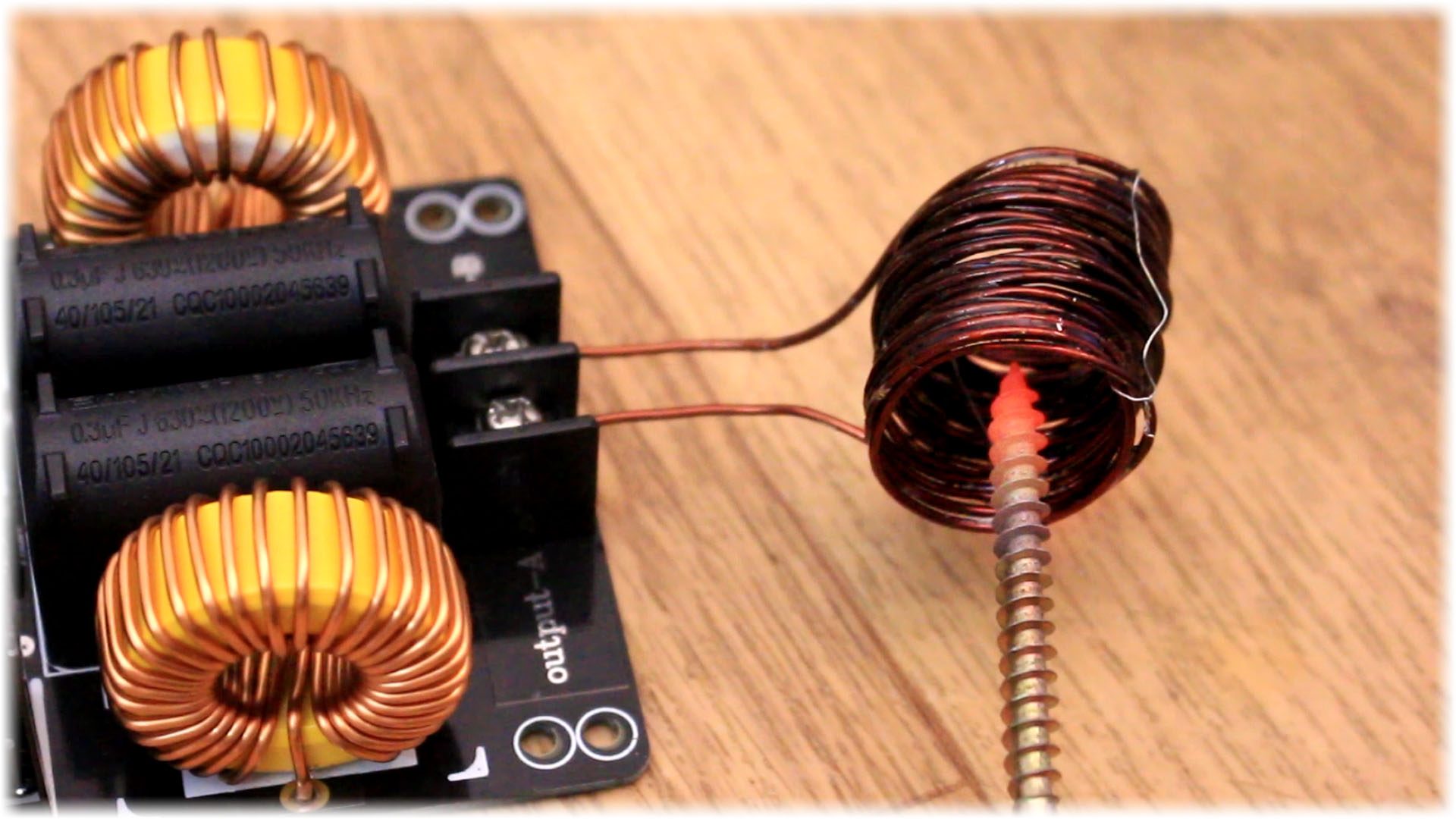
First, in order to learn and comapare signals, I've bought one of these commercial induction heater modules. This one is advertised as a 1000W mdoule. We can see some huge capacitors, some coils and a few more components and at the output a huge coil of thick copper wire. This output coild will create a powerfull osicllating magnetic field and that's what will heat up metals and we will see how. I make a another coil out of some copper wire and place it next to the induction heater coil and as you can see on the oscilloscope we have the oscillating signal of around 100MHz.
In order to understand how this module will heat up metals, we need to understand 3 things. Firtst, how magnetic fields could induce currents inside metals and the oposite process, how current trough wires will create magnetic fields. Then we need to see how the resonance of those coils and capacitors will create high frequency signals and finall, how current will heat up metals. How you could see below, once the module is powered, those high frequency and powerful oscillations will heat up the metal till it glows bright red, in just a few seconds.
Faraday's law of induction is a basic law of electromagnetism predicting how a magnetic field will interact with an electric circuit to produce an electromotive force phenomenon called electromagnetic induction. It is the fundamental operating principle of transformers, inductors, and many types of electrical motors, generators and solenoids. So a moving magnet will create magnetic flux changes inside a coil and by that we could induce current inside taht coil. But what else could coreate magnetic fields?
Well, another componentd than the amgnet that also creates magnetic fields is the coil. Yes, the coil could do the reversed process of current induction. If we apply current trough a coil, a magnetic field will be created so we don't need magnets. A coild could create the magnetic field and induce current in the second coil, just as transformers. So now we know how we could induce current, and that current will heat up our metal. Below you could see how I get the signal from one coil to the other.
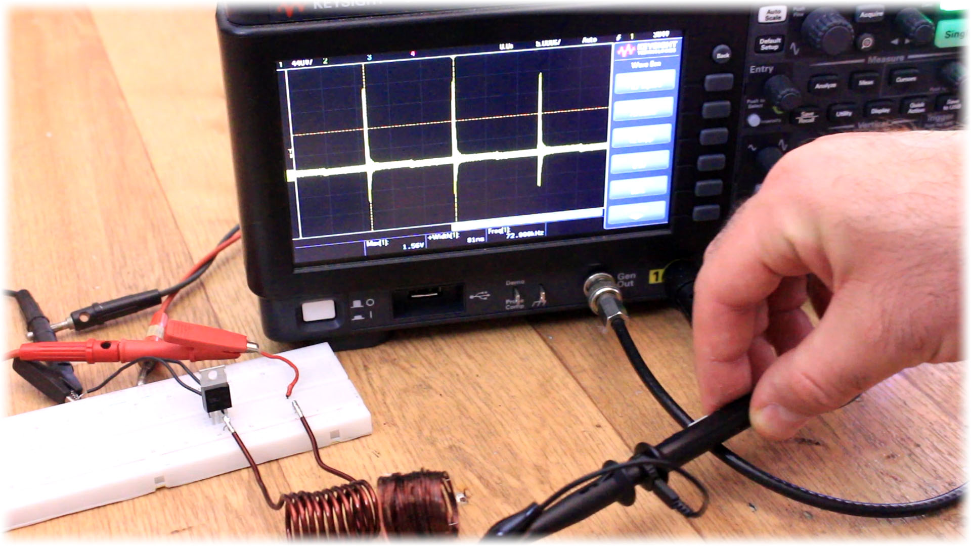
For this example we will use a coil and a capacitor in parallel. This is called an LC tank and if we electronically struck this tank, it will resonate at its resonating frequency. So, if I apply a small voltage pulse and them remove the connection, this will create a fast oscillating signal. I connect that the capacitor and the coil in parallel and touch very fast one cable with 12V to this LC tank. Look below waht happens. After I touch the LC tank, I get on the oscilloscope a fst oscillating signal that is slowly decaying. So, taht's hwo we get our high frequency and powerfull oscilations that will later induce current inside the metal. But our circuit works a bit different. For that let's take a look at the schematic of a basic and simpel induction heater module.
For this example we will use a coil and a capacitor in parallel. This is called an LC tank and if we electronically struck this tank, it will resonate at its resonating frequency. So, if I apply a small voltage pulse and them remove the connection, this will create a fast oscillating signal. I connect that the capacitor and the coil in parallel and touch very fast one cable with 12V to this LC tank. Look below waht happens. After I touch the LC tank, I get on the oscilloscope a fst oscillating signal that is slowly decaying. So, taht's hwo we get our high frequency and powerfull oscilations that will later induce current inside the metal. But our circuit works a bit different. For that let's take a look at the schematic of a basic and simpel induction heater module.
So, as you can see in the scheamtic above, we have 3 coils at the output. For now don't mind coil L3, because that will he the output coil that will create the magnetic field. We have 2 coils, L1 and L2 and one capacitors, C1. We will have resonance as before but this time that will be different and will never stop. As you can see we also have two diodes, D1 and D2 that are connected to the gate of two transistors, T1 and T2. When the signal is first oscillating on C1 there will be a positive voltage on one side of C1 and a negative voltage on the oher side of C1. So one diode will allow current flow and the other one won't. So, one transistor willl eb turned on and the other will be off. But just moments after, because of this process, the polarity on C1 will change and that will activate the second transistor and turn off the other one. And this process will repeat on and on and that will change the current flow inside the L3 coil, because as you can see one enf of that coil is connected to 15V and the other end will be connected to negative or positive and by that creating an oscillating current. That will create the oscillating magnetic field.