In this project we use a GPS module to get the coordinates of any location. Then we get second coordinates and calculate the distance in "meters". It can also give the altitude difference between 2 points. On the screen the coordinates will be printed as well. It uses a color touchscreen TFT display that makes this easy to use.
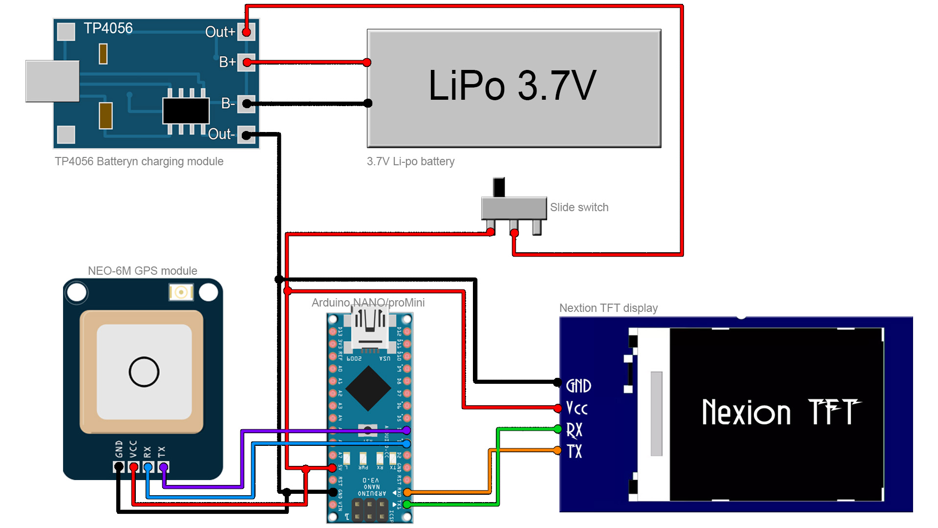
Below you have the schematic for this project with all the connections and components. It is very simple. You can connect everything
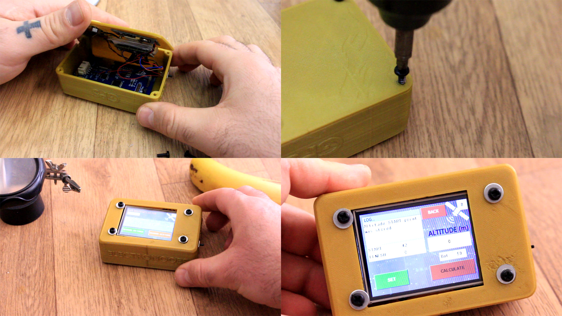
The case is made out of 2 main parts, the top and bottom part. It has spaces for the antenna on the back, slide switch on the side, USB connector to charge the battery and to screw in place the TFT display. Inside it has some supports fot the battery and space to glue the Arduino and GPS module. Print this with PLA material, 2 perimeters, 20% infill and a 0.3mm layer height with a 0.4mm nozzle.
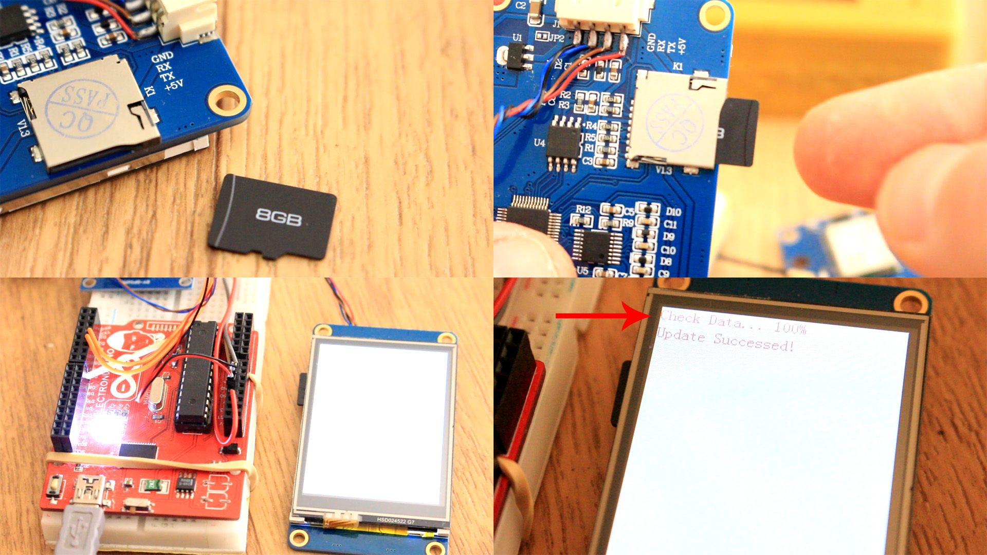
Before anything, we need to upload the enw TFT file I've made in NEXTION editor. See more on how to use this editor and create your onw TFT file here on this link.
So, download the TFT file from below, extract the ZIP file and copy that .TFT file to a micro SD card that is empty. Then plug the SD card into the TFT display and make sure it is powered OFF. Then you can supply 5V and GND from the Arduino and you will see the upload progress on the screen. When you get to 100%, turn off the display and remove the card. Now the new TFT file is uplaoded and ready to use.
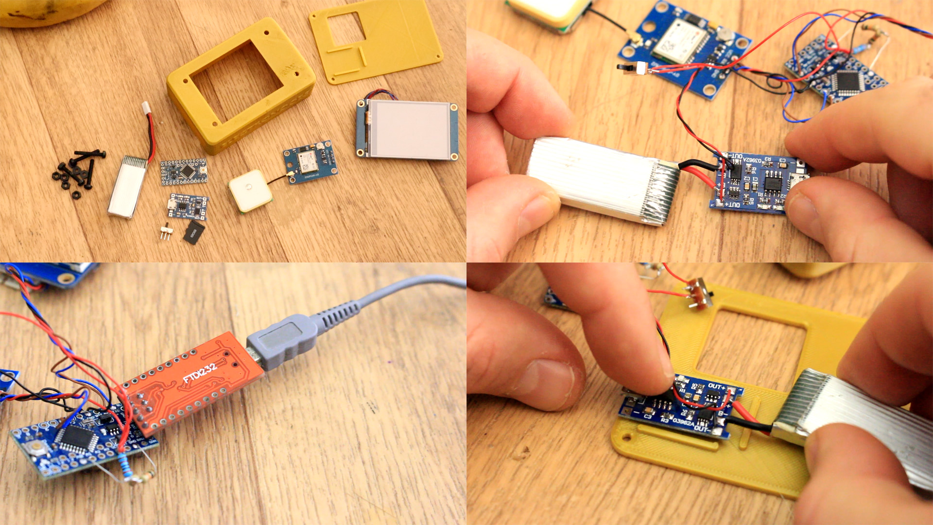
Get all the parts for the project, the case, the modules, Arduino, screws etc. First glue the battery to the charger, to the Sliding swithc, Arduino and everything except the TFT disppaly. Now upload the code using that FTDI programmer. Download the code from the enxt step. Once the code is uplaoded, you could now solder the TFT display wires any time.
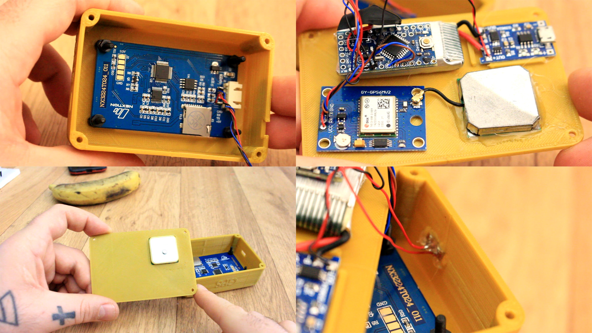
Then I glue the Arduino pro mini on top of the battery and finally, I glue in place the sliding switch on the side hole of the case and that's it. We could now test if it works. After you uplaod the code, solder the Tx adn Rx wires from the display to the Arduino.