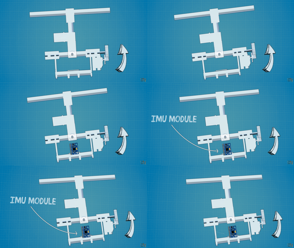

The code is not that complicated. This is how it works. The gimbal moves, the IMU detects the angle change and it changes the PID values. The PID is used to fast react at the angle change. The PID will change the PWM width of the signals connected to the motors in order to keep the same angle. Usually, gimbals have a joystick to change the desired angle. In this case the desired angle will be always 0 till future versions.

	/*We know taht the min value of PWM signal is -90 (usingservo.write) and the max is 90. So that
    tells us that the PID value can/s oscilate more than -90 and 90 so we constrain those values below*/
    if(roll_PID < -90){roll_PID = -90;}
    if(roll_PID > 90) {roll_PID = 90; }
    if(pitch_PID < -90){pitch_PID = -90;}
    if(pitch_PID > 90) {pitch_PID = 90;}
I map the values to a range between -90 and 90 degrees. But you could change that value. Also, my gimbal had a maximum of -/+20 degrees for thr X axis and -/+50 degrees for the y axis. Then we write these values using the analogWrite() function and control the servos.