


As in the last example tutorial, we will use infrared light to send data. But the signal in taht tutorial was encoded. In this tutorial, we will build our own IR remote and receiver. We will sue the UART port to send data and some IR LEDs to send the signal to the receiver. The receiver will eb made out of a phototransisitor that will detect the infrared light pulses and with an Arduino we can read the data and control stuff with it.
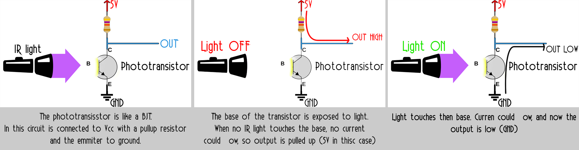
First, let's see how the phototransistor works. It is jsut like a BJT transistor but the base is exposed to light. A certain material makes this component only sensible to infrared rays. When IR light touches the base, the transistor will let current pass. If the emmiter is connected to ground, as we can see below, the output will be low in thisc case. But, when no light touches the base, current can't pass so the output is pulled up witk a resistor of 1k for example. That's is, with this setup we can detect pulses of IR light. All we have to do is to connect the output to an Arduino.
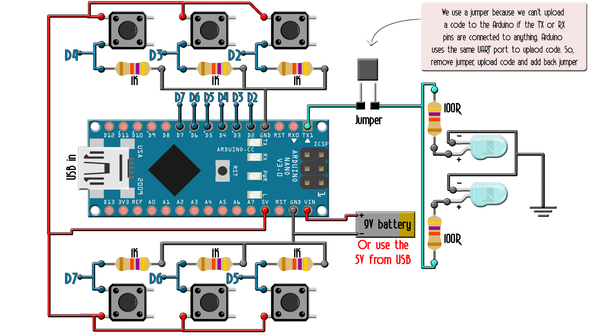
Below we have the transmitter schematic. I've used 6 buttons but you could add more up to the limit of the Arduino inputs. Each push button needs a pullsdown do GND so when is not pressed the output will be low. When pressed will be high. To send signals, I've used two IR LEDs to increase power and a 100 ohms resistor to limit the current. To supply the circuit you could add a battery to the Vin pin or use the USB cable. Also, the jumper is used to open the TX circuit when uploading the code. If the UART port is used when uplaoding the code, might give errors.
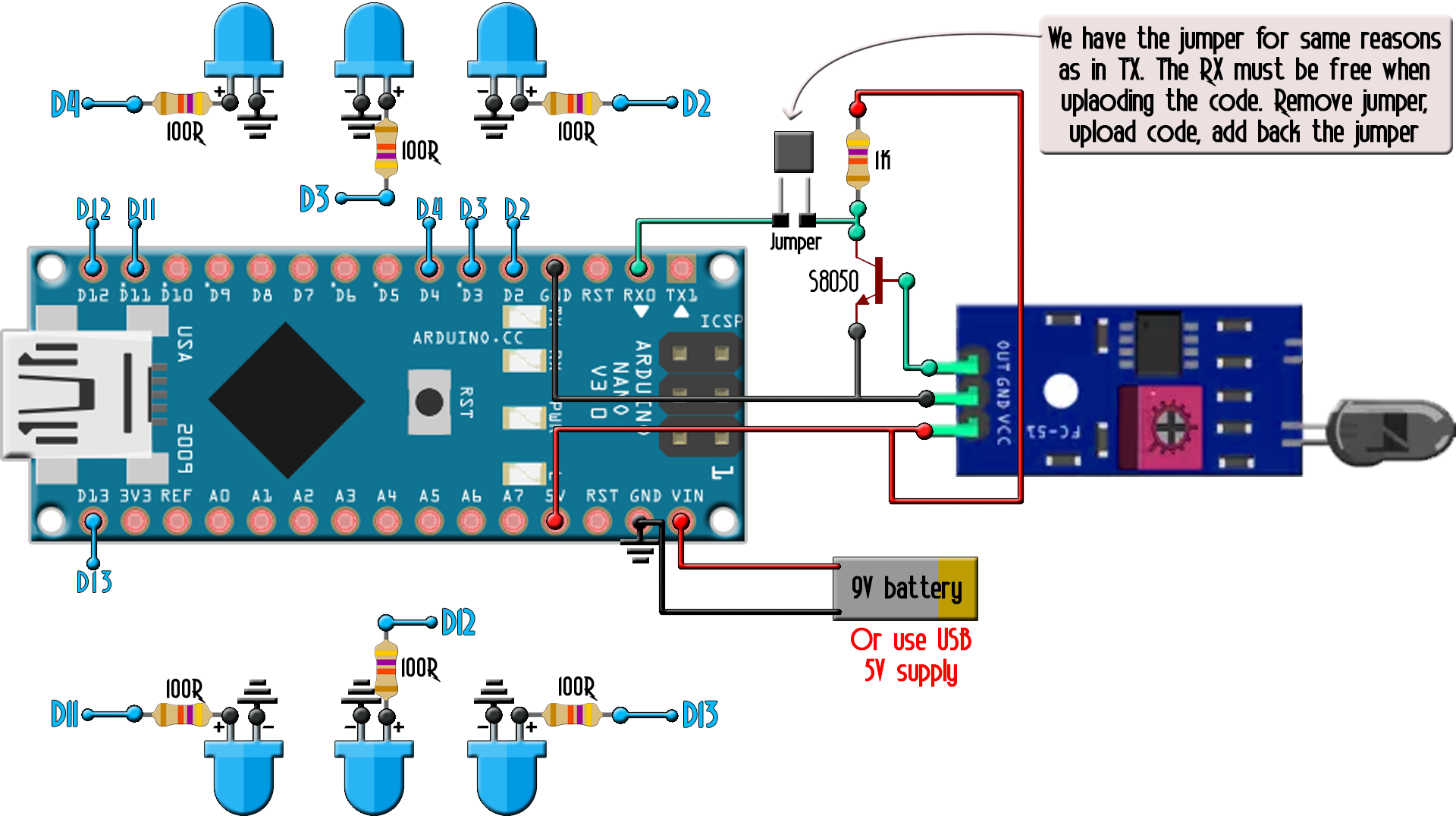
Below we have the receiver scheamtic. As you can see I've used the infrared sensor module but without the IR LED, only the phototransistor. Alos, you can see I've placed an extra BJT transistor between the module output and the RX input of the UART port. Why? Well, the output from the sensor is always low and high when it receives light. But the UART communications is just the oposite. It has to be always high and low when receiving data. That's why I've placed the BJT with a pullup of 1k, to invert the signal that goes to the RX pin. Then, I have 6 LEDs, each for one pressed push button from the transmitter. Once again, we have the jumper for when we upload the code.
The code is more than easy. We define out inputs and outputs.
//Codes to send. Change if you want. Up to 8 bits so 0-255
byte LEFT_TOP_CODE = 0x04;
byte LEFT_MID_CODE = 0x08;
byte LEFT_BOT_CODE = 0x0C;
byte RIGHT_TOP_CODE = 0x10;
byte RIGHT_MID_CODE = 0x14;
byte RIGHT_BOT_CODE = 0x18;
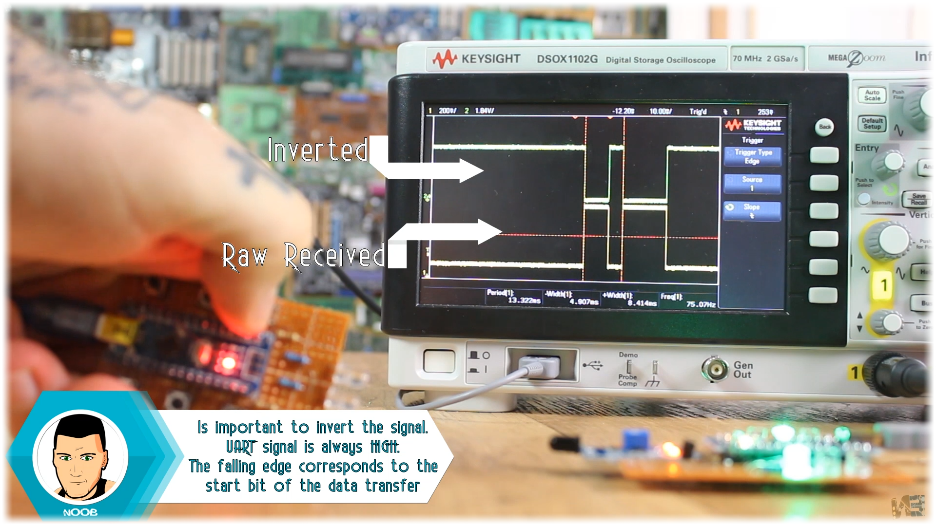
Upload the code to the transmitter Arduino and put back the jumper. Now, each time I press a button, a different UART 8 bit data is sent as we can see below on my oscilloscope where I ahve both the raw data and the inverted one.
The receiver code is also easy. We start the serial communication with the same baud rate, 300 bauds. If the Serial.read function returns a number above 0, that means we will receive data. We store the byte. If the received data is one of the sent bytes, we invert the LEDs state and by that turn them on and off. Change the code to adapt your project if you want to do more than turning LEDs on and off.
if(Serial.available()>0)
  {
    received = Serial.read();
    //Serial.println(received); //uncomment for debug

    //If the received byte is one of the codes, we change the LED state
    if(received == LEFT_TOP_CODE)
    {
      LEFT_TOP_STATE = !LEFT_TOP_STATE;
    }
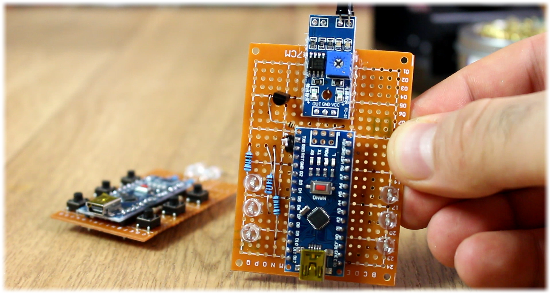
Upload the code to the receiver Arduino and put back the jumper. Now supply both transmitter and receiver and press the buttons. You will se that for each button, you could turn on and off the LEDs on the receiver.


