


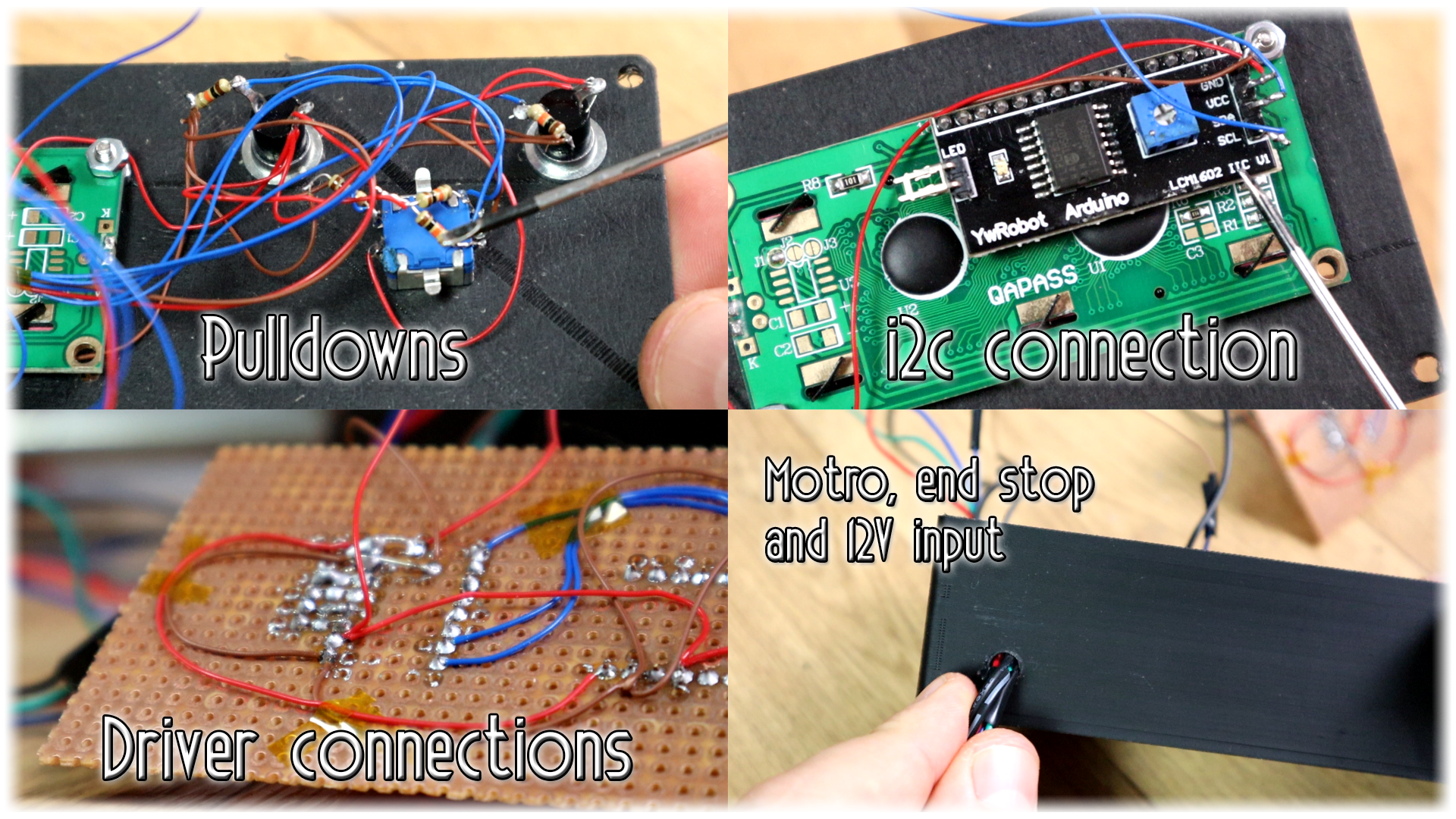
Ok, below you have the full schematic of this project. Pass the wires from the motor and end stop switch inside the case through the back hole. Also the 12V from the transformer and connect that to the Vin of the arduino and to the Vmot of the step motor driver. Remember to add pulldowns to each push button and to the end stop switch.
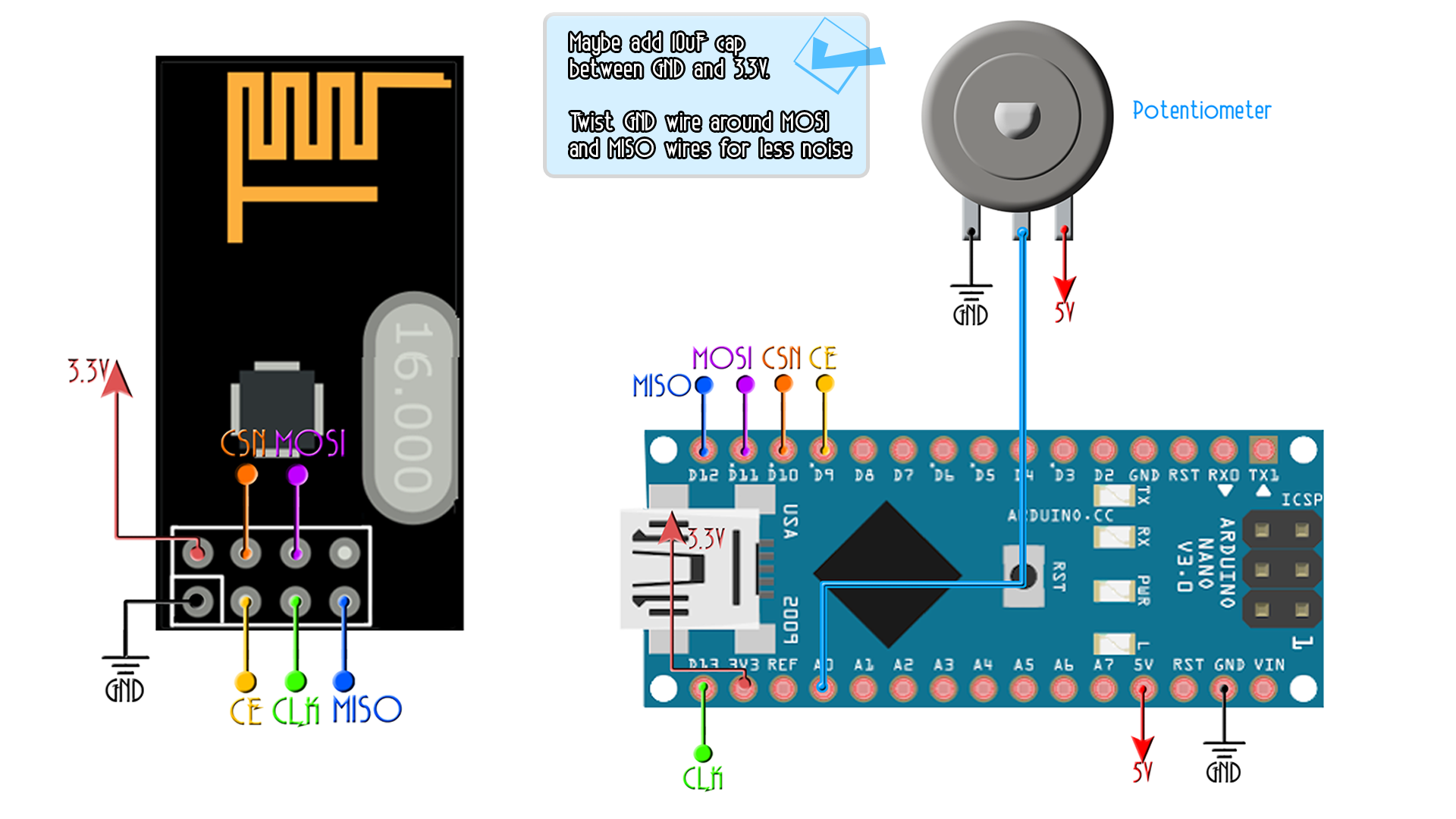
All buttons have pulldowns to ground so when the button is pushed, it will jump to a high state. Finally, I make the connections from the Arduino to the step motor driver. I connect the enable, the direction and step pins to digital pins 5, 6 and 7 and we are done. I pass the 12V transformer wire through the case hole and connect positive to the Vin pin of the Arduino and ground to ground and also supply 12V to the step motor driver. Now pass the motor and end stop wires inside the case and now let’s take a quick look over the code.
What I want it to do is to be able to use the encoder and enter a menu. Inside the menu, I could home the slider or change the speed. Once the speed is selected, you could select sliding to the right or to the left using the buttons.
Now, on the left side we have an end stop so the code could easily know when to stop. But on the right side we don’t have one. So, the code will have to count the maximum amount of step. We calculate how many steps we need for one cm, then it is very easy to know how many steps we need for 1 full meter. So once the slider is homed, the position step counter in the code will be set to 0.
if(Position_steps > 10000)
    {
      digitalWrite(Enable, HIGH);      //Disabled
      Slide_right = false;
    }
    digitalWrite(Enable, LOW);      //Negative enabled
    digitalWrite(Direction, HIGH);   //GIGH for Right
    digitalWrite(Step,HIGH);
    delayMicroseconds(step_delay);
    digitalWrite(Step,LOW);
    delayMicroseconds(step_delay);
    Position_steps = Position_steps + 2;
As you can see in the part above, when the amount of steps is over 10.000 we stop the driver. If not, we create a square vawe with a width of the "step_delay" value. After the square wave, we increase the step amount by 2 since each pass from high to low and low to high of the square wave will be a step.
The code is quite easy but probably a bit long. Remember, you will need the i2c liquid crystal library if you use this kind of LCD screen so make sure you download it from below and install it on to your Arduino IDE.
See my other rotary encoded menu video below to learn more about this project because since I’ve already done that, I won’t explain it step by step.
But any way, now, in the code, each time the data or clock pins of the encoder or any of the other buttons will change their state, we create an interruption (read all the comments in the full code). By rotating the encoder, we increase or decrease the menu position or the speed amount. Please, read all the comments in the code in order to understand more.
Now, in infinite loop, if one of the left or right buttons is pressed will activate the enable pin for the step motor driver, select the direction with low for left and high for right, and create a square wave on the steps pin. The delay between the high and low state of the square wave will give us the frequency and that will control the rotation speed of the motor. Read in the code how to calculate your delay time depending on the pulley size.
/*
   * The speed is seconds per meter, so how many seconds the slider needs to make one meter
   * We know that in my case, each rotation needs 200 steps
   * Also, my pully has a perimeter of 2cm so each 200 steps I make 2cm, so for 1m I need 10.000 steps.
   * That's why below I multiplay the speed in seconds by 10.000 and then divide it by the amount of steps
   * we need for only one cm and the delay is expresed in microseconds. Also see above the perimeter of the pully
   */
   step_delay = (10000 * Speed)/steps_per_cm;
   if(Slide_left)
   {
Download the code from a link below, compile, make sure you have the connections as in the schematic and upload the code. And there you go.
This is how this works. When I start the slider, the first thing it dose is homing itself and by that reset the position. Then I press the rotary encoder and select the speed menu. In this case the speed is expressed in seconds. This will be the time it takes the slider to make a full meter. I set is to 4 seconds.
I press the rotary encoder again and exit the speed menu and we are ready to slide. I press the R button and the slider starts moving to the right till it reaches the maximum amount of steps. Remember that timing belt is much better if you want precision so once I’ll receive the 3 meters belt, I’ll use that. The slider stops if it reaches maximum sliding steps, or if any of the buttons is pressed.
There you go my friends. The slider is quite strong made with metal tubes. It can easily carry my DSLR Canon camera and with this cheap camera adaptor, you could set any angle. If you would like to support me, check my Patreon page and by that be able to see when I post my videos one day before.


