
 About me
  History
  Let's learn
  Contact us
  Arduino tutorials
 Circuits tutorials
  Robotics tutorials
 Q&A
Q&A Blog
Blog  Arduino
  Circuits
 Robotics
  Modules
  Gadgets
  Printers
  Materials
  3D objects
  3D edit
  Donate
  Reviews
  Advertising


Arduino based RPM meter (3D printed case)
The circuit
If we analyze with the oscilloscope the output signal while the shaft is spinning we can see some errors. The signal is not a perfect square wave and has a sinusoidal shape. In order to improve the signal and obtain a perfect square wave we should use an operational amplifier. I’ve use the LM324 OP amp. Connect the output from the sensor to the positive input of the OP amp and the negative input to a voltage divider made with a potentiometer. In this way, we could regulate the sensing distance of the sensor depending on the intensity of the light.
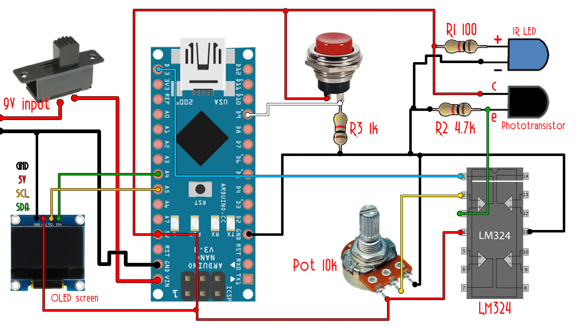
Ok, as you can see in the schematic above, we have a 9V input from the battery. The slide switch will turn on and off the entire system. Connect the output from the switch to the Vin pin of the arduino. Also connect ground. Next you should supply 5V and connect GND to the OLED screen and the LM324 amplifier. Also connect 5V to the push button. Add a 1k pulldown resistor to the push button. In this way when the button is pressed the D9 input will be high and when the button is released the input will be low. We will use this button to put the arduino in low power mode when not measuring.
Add a 100 ohm between the positive pin of the IR LED and 5V. Also connect a 4.7k ohm between the emmiter off the phototransistor and ground. Now connect the emmiter to the positive input of the LM324 OPAMP. Create a voltage divider between 5V and groudn with a potentiometer and connect the middle pin to the negative input of the LM324 amplifier. Using this potentiometer we could adjust the detection distance/intensity. Finally connect the amplifier output to digital pin 13 of the arduino. The circuit is ready.
Using this black and white paper I check the functionality. The black color should absorb all the light so no light will reflect into the transistor base so the circuit is still open. When white color is placed in front of the LED, the light reflects and hits the transistor base closing the circuit. So, imagine a white stripe on the exterior of the motor. Each time the stripe pass in front of the sensor we will have 0 volts at the output and 5 volts in the rest of time.
Let's build this thing.
Building it
Ok, I've used a 3D printed case. You have the download link with the STL belwo. Download it and print the parts using 2 perimeters adn 20% infill. I've used my Anet A8 printer and a 0.3mm nozzle. Use support material for the parts with the (use_support) file name.
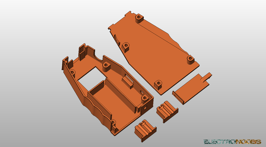
Download the STL files for the 3D printed case here: