Months back I've made an Arduino based multimeter that was able to measure quite well voltage, current, capacitance, inductance and resistance. That was soldered on a homemade PCB and with wire connections, you can see that tutorial here. But that version had some errors. First of all the circuit was a mess becuae I wasn't using a professional made PCB and we had a lot of wires. Then, I've used the wrong current sensor so thet mode was not working. Also, the worst thing was that we had different inputs for each mode. Usually, multimeters have just only one input for the probes and then a rotary switch to change between modes. That's exaclty what I've made in this second version and also a few more improvements. Now we have auto scale mode for all the measurements, we can also measure negative voltage because we use the ADS1115 ADC sensor in differential mode, we can also measure AC voltage because the circuit has a full bridge rectifier and a few more improvements...
This project is easy and the part list is quite straightforward. The Arduino will control everything. To detect the angle of rotation and by that know when the ball is upside down we will use the MPU6050 gyro module. To print the text we need an OLED display and to play sounds we will use the DFplayer with the SD card and a small speaker. We need a 18650 battery and a charging module and to get 5V we need a small boost converter. We will also need glue and small wires.
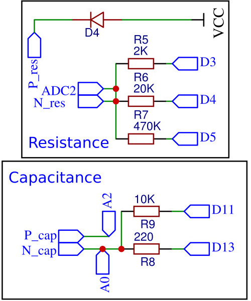
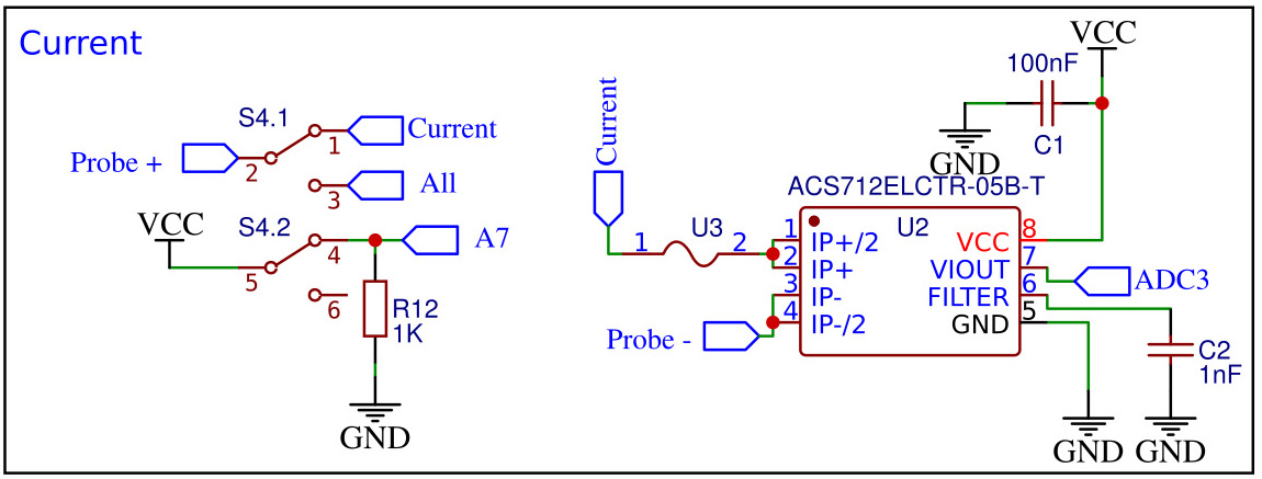
The schematic could be a bit tricky. But I've separated all parts. The first block should be the one in the middle witch is the rotary switch. As you can see the input from the probe is divided into 4 outputs for voltage, resistacne, capacitance and inductance. Current is done separatelly with a sliding switch (S4.1). The first measure block is the voltage one. As you can see we have the input from the probes connected to the full bridge rectifier and then we have a capacitor so we can store the voltage for AC mode. Then, that voltage is connected to some dividers and the output of the dividers to the ADC0 and ADC1 of the ADS1115, so in this way we can measure in differential mode and be able to measure negative voltages too.
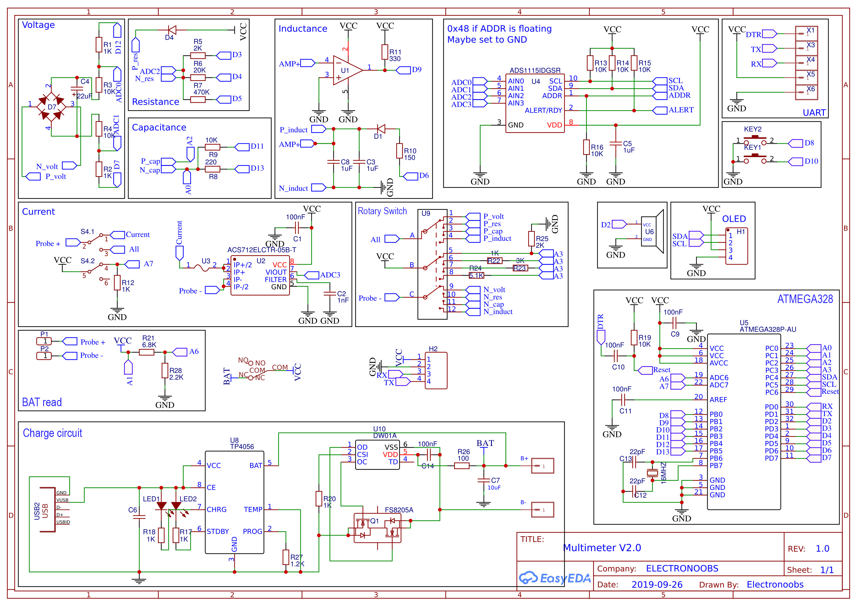
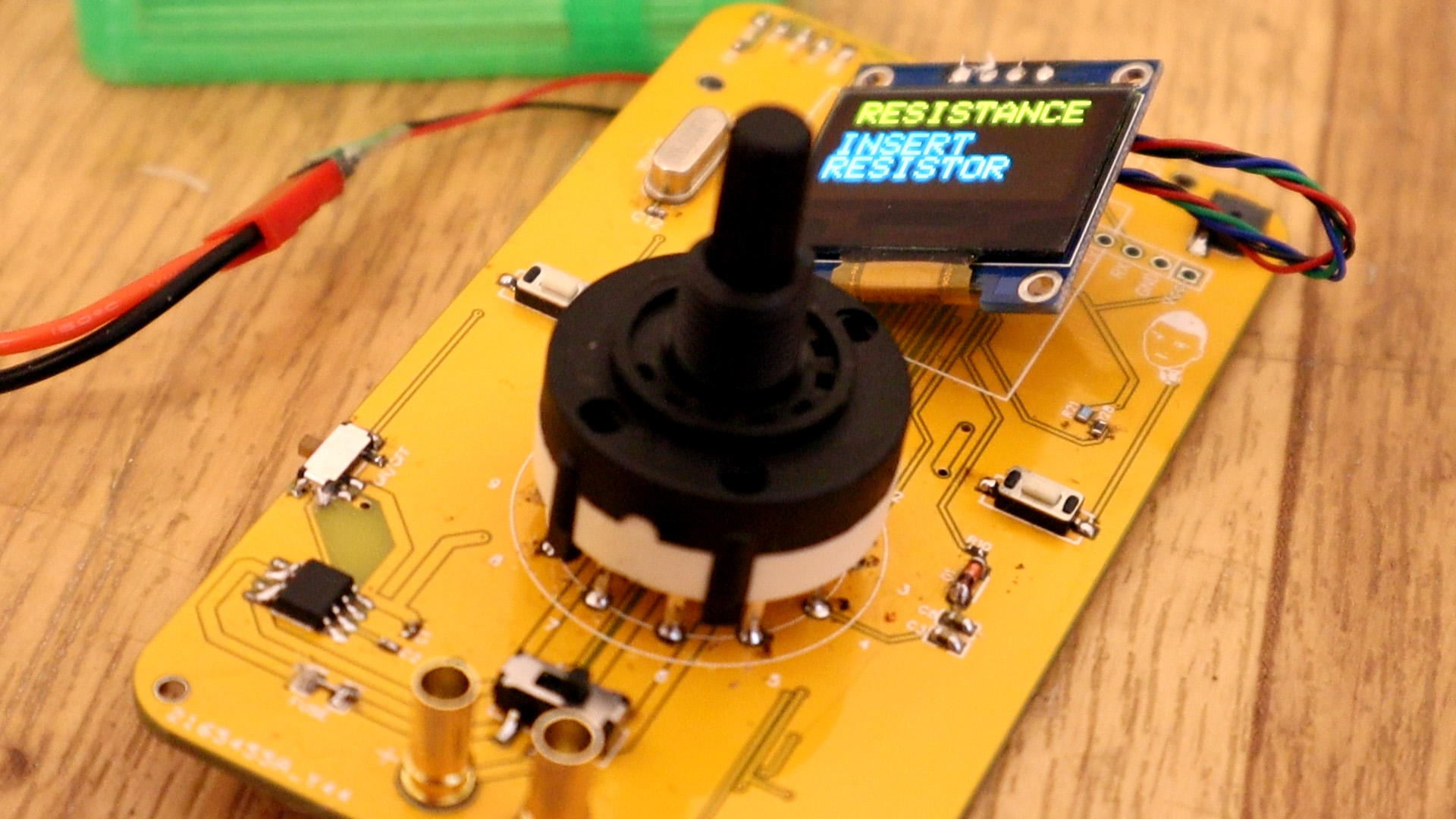
Next we have the blocks for resistacne and capacitance. Resistacne is easy. In the code, by changiong D3, D4 adn D5 to "LOW" we create a virtual GND to those pins. So, we can select fropm different voltage dividers in order to select scale. Then we measure the voltage with the ADC2 input of the ADS1115. We know the divider value and the measured voltage, so we can get the resistance value. Is that easy. You can see more about resistance measure here on this tutorial.
Now for capacitance mode, we first charge up the capacitor with one of the D11 or D13 pins, depending on the mode. Then we measure the time it takes to discharge to 63.2% and then we use the time constanct to get the capacitor value. See more on the tutorial here.
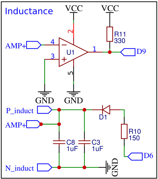
Next, we have indcutance meter. here we have an "LC tank" made with those 1uF capacitors in paralel which make a 2uF cap, and the coil that we insert. An inductor in parallel with a capacitor is called an LC circuit, and it will electronically "ring" like a bell. Well regardless of the frequency or how hard a bell is struck, it will ring at it’s resonating frequency. We will electronically strike the LC bell, wait a bit to let things resonate, then take a measurement.
So what we will do is applying a pulse signal to the LC circuit. In this case it will be 5 volts from the arduino from D6. We charge the circuit for some time. Then we change the voltage from 5 volts directly to 0. That pulse will make the circuit to resonate creating a cushioned sinusoidal signal oscilating at the resonant frecuency. Using the OPAMP we pàss that signal to square waves and then with the ARduino at pin D9 we measure the pulse lenght and bt taht we obtain the frequency. With the frequency, we get the inductor value because we already know the 2uF value of the capacitor. See more here.
Current meter is simple. We connect the input to the ACS712 amplifier which is specially designed for current measure. It will give an analog output according to the current value and we know the gain. In this case I'm using the 20A model adn the gain is 100mV/A output. So all we do in the code is to measure the analog output and then by knowing taht each 100mV is 1A we can get the current value. You have some more theory here.
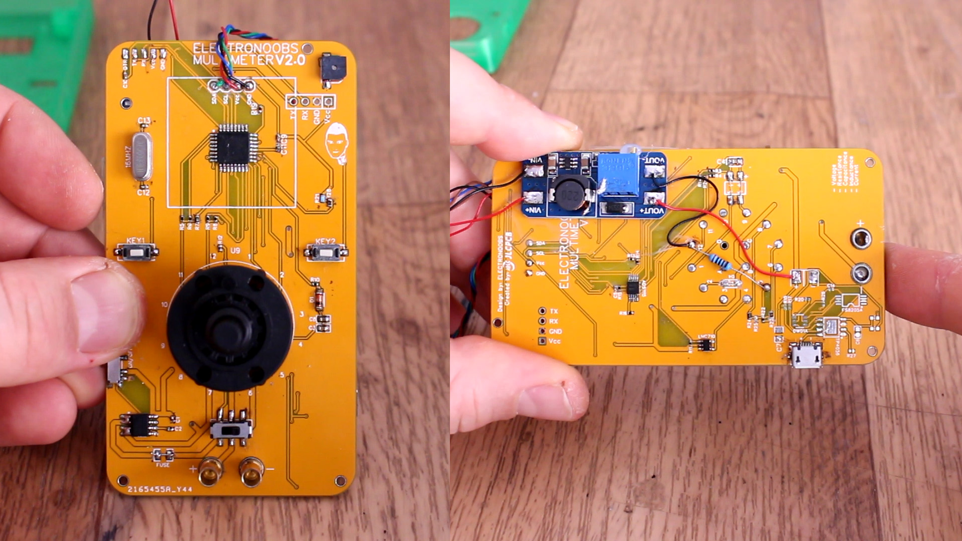
Once you see the PCB you will notice that on the back we have 2 pads for the batery (+ and -) and the charging circuit. We won't use these parts for now and this is why. In order to properly make calculations in the code, we alo need to know the refference voltage of the battery. For that I've placed a divider on the scheamtic made with resistors R21 and R28. The input of that divider is the battery and using A6 we could measure the refference in the code using the internal refference of 1.1V. But, dum as I am, if we set the analog refference to internal, then all analog measurements will eb set to "INTERNAL" and we don't want that. So the solution is this:
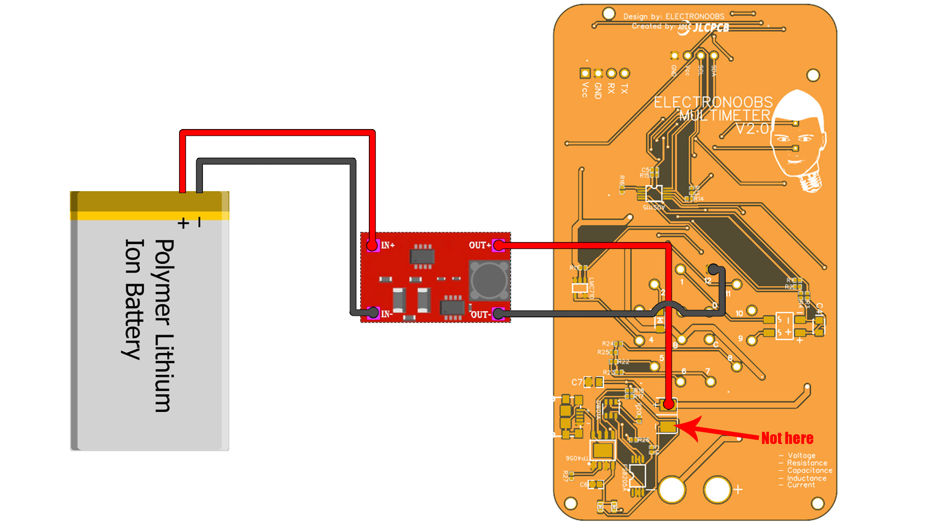
Instead of measuring the battery value, what I've done is place a boost converter at the input that will always supply 5V. So now we know that the input will ALWAYS be 5V. But with this configuration we can't use the battery charger circuit. So, stay tuned for a future update of the circuit and PCB. So get the boost converter and set it to exactly 5V and then connect it to the PCB like shown above. One pin to the + pad and the other to GND of the PCB, NOT to the "-" pad! So don't solder any components from the "Charge circuit" block from the schematic.
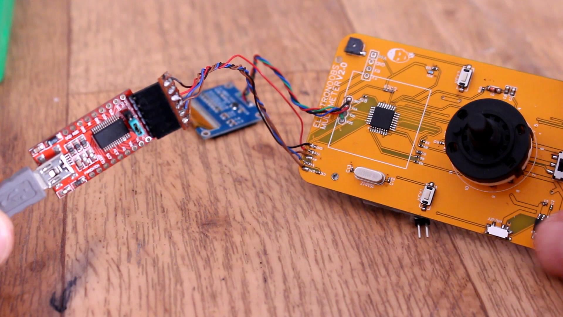
Ok, get the GERBER files from below and order the PCB, or mount the same circuit on a prototyping PCB if you want. Anyway, get the PCB and let's start soldering components. But that must go in this order. First, we have to solder the ATMEGA328 and the basic components. That means all the components in the "ATMEGA328" block from the scheamtic. The chip, the crystal, the pullup R19, the small 22pF capacitors for the crystsl and the DRT C10 capacitor of 100nF. Also solder C9 and C1 of 100nF as well. With these components the IC should work. To test if it dose, connect the FTDI programmer to the UART pins, DTR to DTR, RX to TX, TX to RX, GND and Vcc and upload a code. For example uplaod a simple counter and print that on the monitor. If you get results, then the IC is working.
If the IC works, you can now solder all the other components from the scheamatic. Use a lot of flux and food solder beacuse the 0402 pads are very small. Or, if you want go here to easyEDA and get the schematic and make your own board with bigger components. Connect the OLED display with thin wires. Connect and glue the battery and the boost converter on the back. Add the 4mm bullet connectors as probe input. Check the rotary switch pins. The swithc has 3 inpouts and 12 outputs. The PCB has 4 inputs. You must use inputs A, B and C. D is not used. Also, make sure which is output "1" of the roraty swith and make sure it will be connected to hole 1 on the PCB. Is time for the code.