Panel Cookies
yt_link
insta_link
fb_link
twitter_link
Blog#25 - Smartwatch baord

Last tutorials

All about Arduino PWM frequencies
Debug Arduino and ESP with PlatformIO
Homemade Best Two Hand Multimeter with Arduino
Homemade Baby White Noise Generator
Measure AC RMS with Arduino

ADVERTISERS


Arduino smartwatch board
Help me by sharing this post

Go back ↞ See other blog→

Author: Electronoobs
16/10/2018
So, I'm working on a new project. What I want to get is some sorto of "smart" watch. It will definitelly show the time and date. So for that, the board I've designed has a real tiem clock chip on it. That will get the real time if we always have the battery connected. The baord will have a bluetooth connection, and that means it could be connected to an Android smartphone. Using an App that will get information from other Apps, I'll send data to the bluetooth module. This data should be something like incomming call or message, any alert, maybe Whatzap message and so on. I'm not sure yer, but for now I have the baord and that's the first step.

To order your boards, use JLCPCB.com and select your color.


One big change compared with my other baords, is the use of a tiny quad-flat no-leads or so called QFN package for the microcontroller. It's still and ATmega328p but it is very tiny so it might be dificult to solder. But in this way, the space on the PCB will be way less so I could place more components.

The bottom aprt of the back PCB is full with components for a 3.7V battery charger based on the TP4056 chip- It has a USB connector and these components will regulate the voltage and current in order to cahrge the battery. So, when the battery is low, we just plug it to the USB connector and charge it just as other smartwatch.


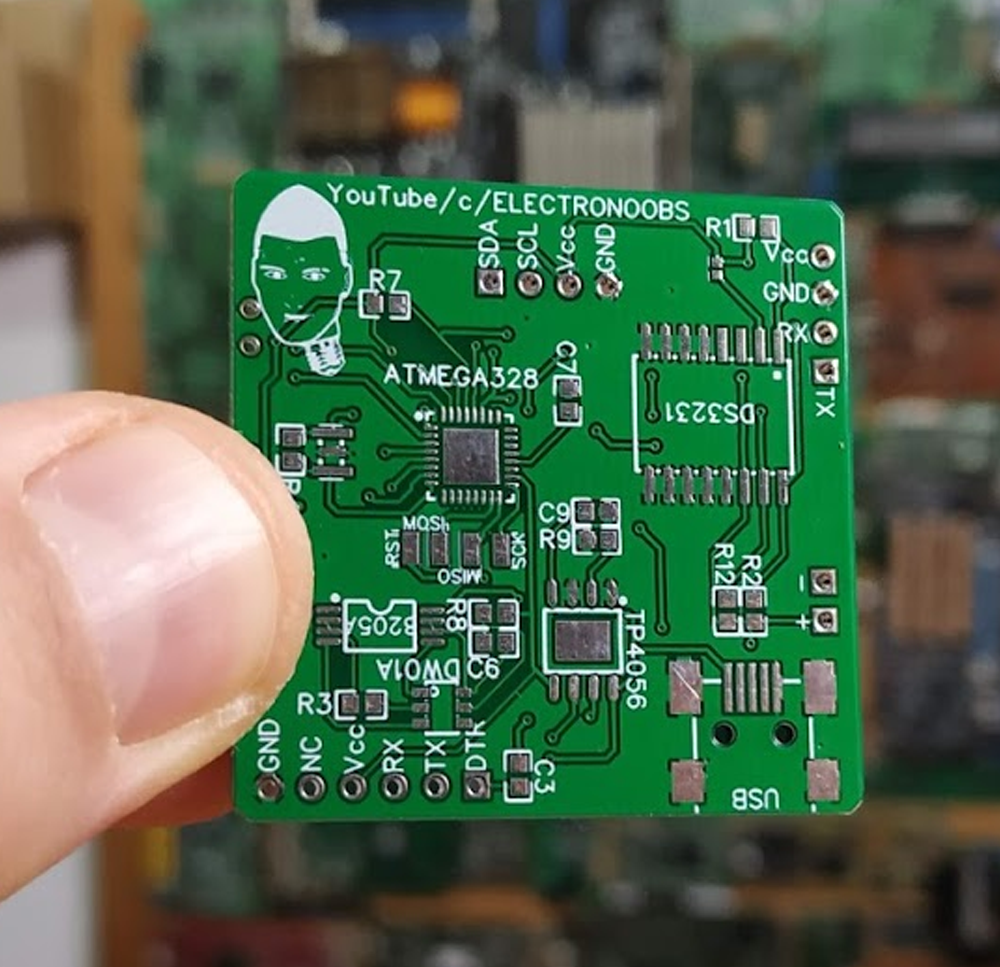
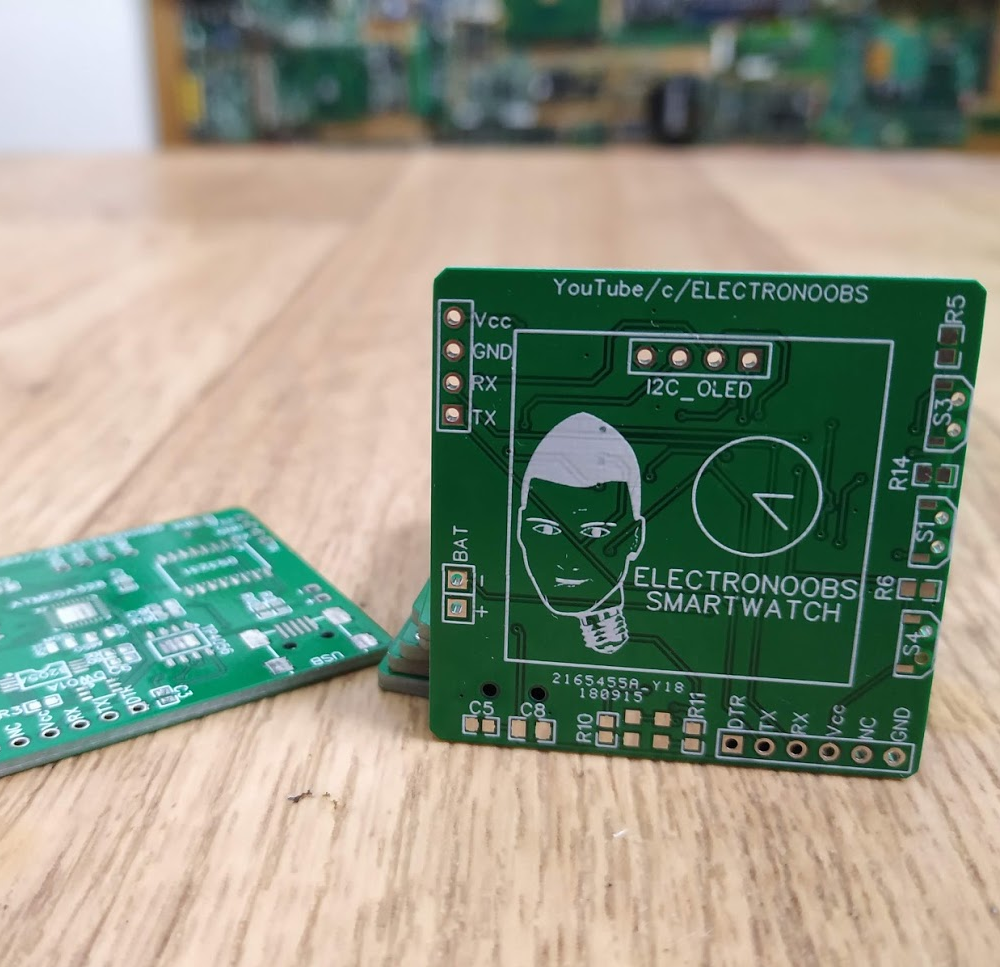
We can also see the DS3231 chip, which is the real time chip. Using i2c connection, we could get the real time from this chip. On the front part of the board, on top,we have 4 pins for the i2c connection of an OLED screen, since that is what I'll use to show stuff. On the side we have 3 push buttons in a 90º format. On the left side we can see the pins for the UART connection of the Bluetooth module and on the bottom we have the pins we will use to program the baord using an FTDI mdoule.

That's it. Stay tuned for the full tutorial on my YouTube channel. I really hope you will like this first version, since I'm sure I'll have more version than just this one. Keep up.


Help me by sharing this post

Go back ↞ See other blog→


Affiliate Disclosure

ADVERTISERS


PCBWAY PCB service


Curso Arduino Online nivel Intermedio