Author: ELECTRONOOBS
27/11/2018
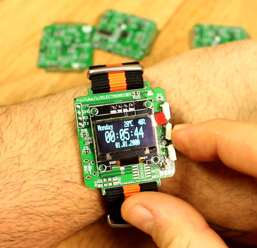
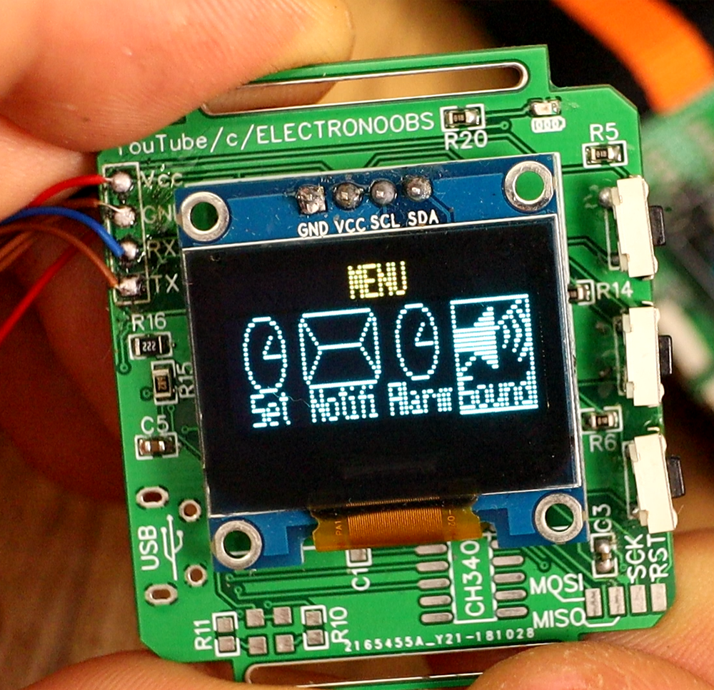
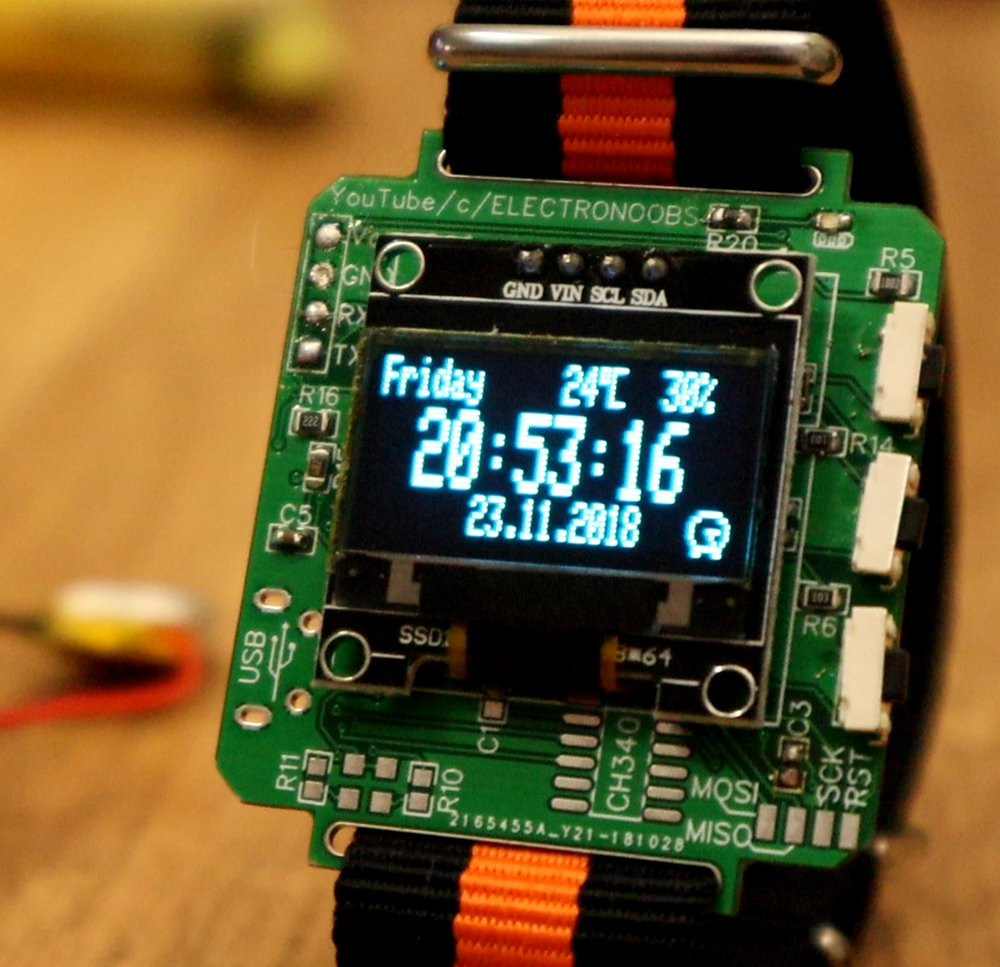
I've received the boards a few weeks and I've started soldering components and making tests. Is then when I realized the layout had some errors. Unfortunelly, I've used the wrong pad for the USB, so the Vcc pin and GND are reversed. So I can't use the USB connector. That also means I can't program the board by USB but neighter charging the battery. The board has an FTDI chip and a charging circuit, but without the USB those can't be used.
Any way, I was able to program the chip using and external FTDI programmer. So, after I've soldered the ATMEGA chip in a QFN format, the needed resistors and capacitors but also the RTC chip, the small buzzer and the push buttons, I was able to upload a few versions of this smartwatch firmware.
To order your boards, use
JLCPCB.com and select your color.


 See other blog→