Author: ELECTRONOOBS
20/11/2018
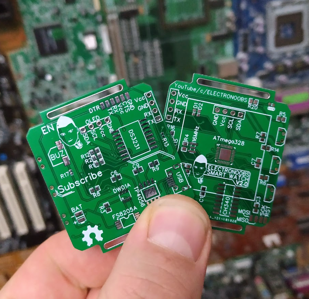
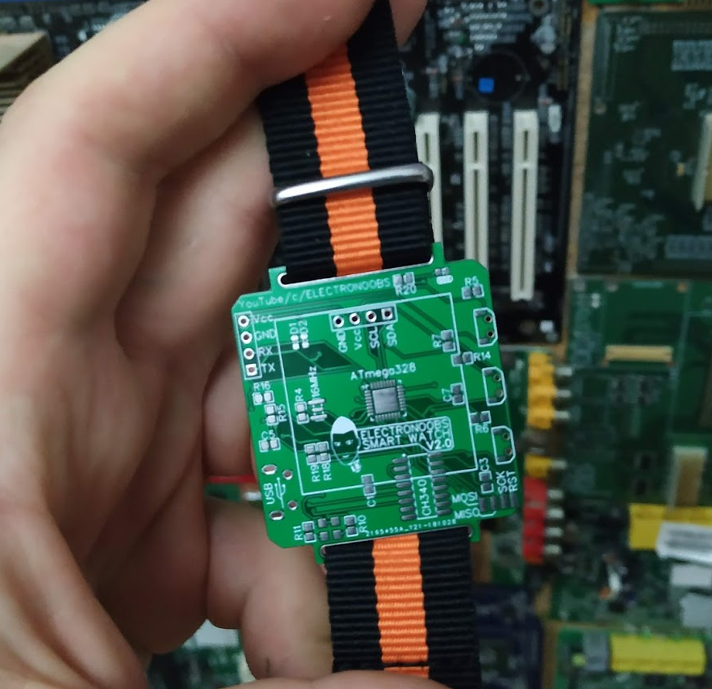
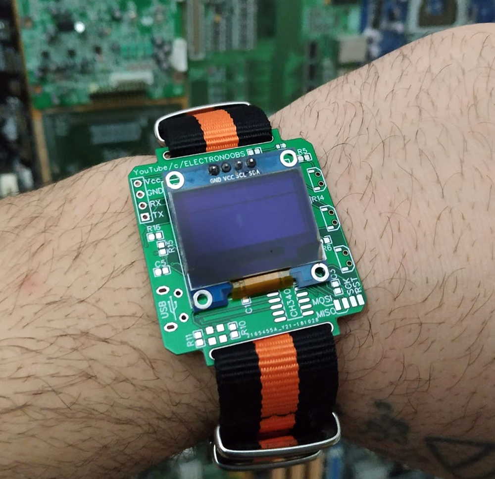
This is my new boar for a smartwatch project. Please see the other version
on this post in order to compare the final results. First of all, the shape. I realised that giving the space for a watch belt would be a big advantage. Now, once the board is finished, I can put a small plastic 3D printed case, but put the belt on the holes that are specially made for a watch belt. The holes are actually vias with a 20mm width. Let's talk about the rest of the board. Well, now, this new version has a FTDI programmer, so we could program it directly with a USB connection instead of using an external FTDI module conected to the UART pins. The used chip is a CH340 that is connected to the RX and TX pins of the ATmega chip. Also, as you can see the ATmega328 chip is very small and now, it's on the top layer of the PCB.
To order your boards, use
JLCPCB.com and select your color.


 See other blog→